Printer 710_810 v8 Transportation.pdf - 第68页
TRANSPORT ATION MAJOR RE LOCATION 34.68 Technical Reference Manual Chapter Issue 7 Oct 06 13. Lock of f all five mounting feet using the l ocknuts. 14. Recheck the machine is level. 15. Recheck the machine hei ght has no…
TRANSPORTATION
MAJOR RELOCATION
Chapter Issue 7 Oct 06 Technical Reference Manual 34.67
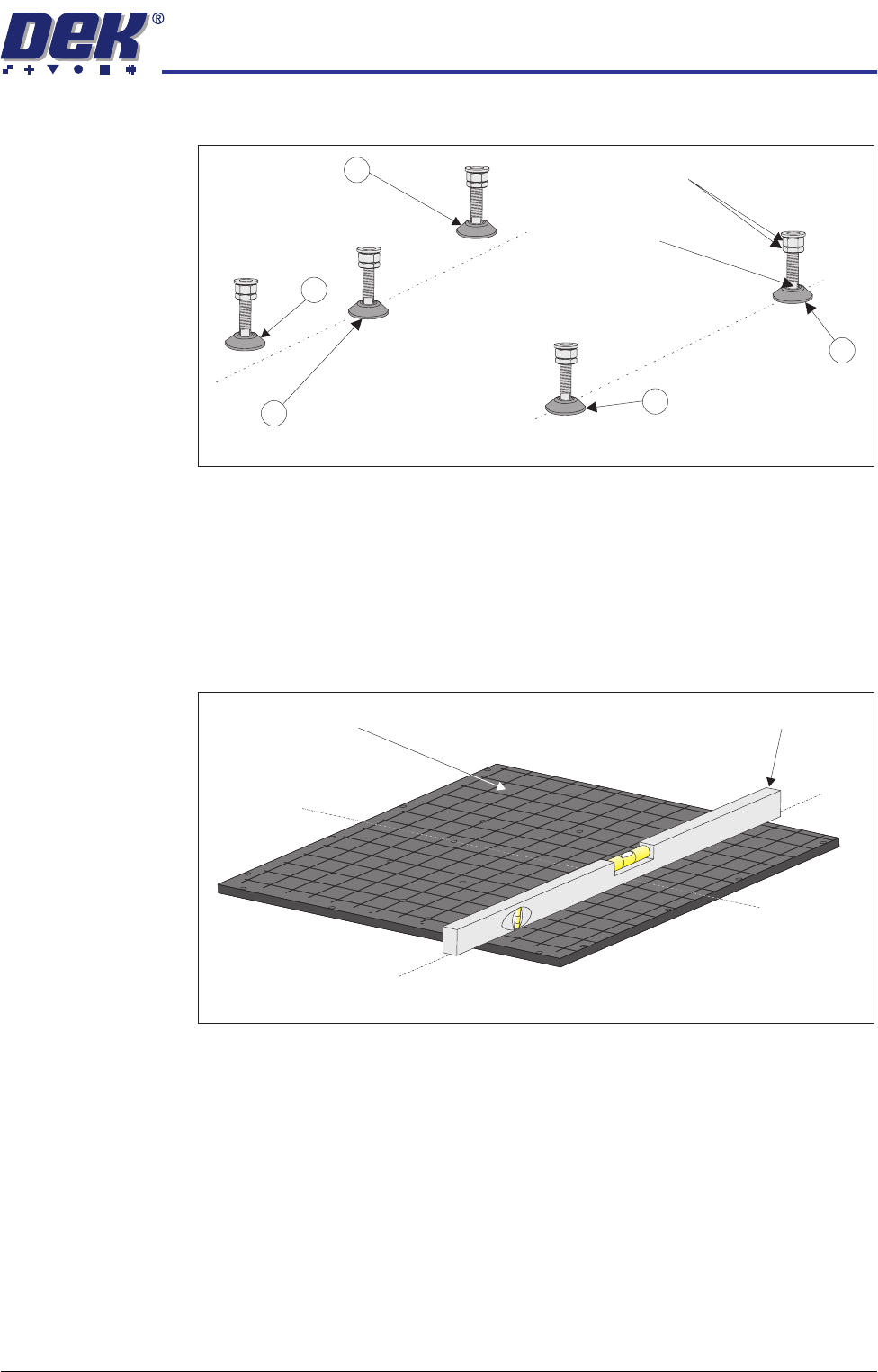
1. Adjust the front right hand foot (1) to achieve the desired height.
2. Adjust the front left hand foot (2) to approximately the same height.
3. Lower the rear centre mounting foot (3) so that it is in contact with the floor.
4. Raise the rear left (4) and rear right (5) mounting feet so they are not in
contact with the floor/leg spacers and the machine is supported on the front
two and rear centre mounting feet.
5. Place an engineering level on top of the manual tooling plate along the front
row of screws running from left to right.
6. Adjust the front left (2) mounting foot to level the machine in the X direction.
7. Move the engineering level along the centre row of screws running from front
to back.
8. Adjust the rear centre (3) mounting foot to level the machine in the Y
direction.
9. Repeat Steps 5 to 8 until the machine is level in both directions.
10. Carefully lower the rear left mounting foot (4) so that it is in contact with the
floor/leg spacer. Check the machine level has not been disturbed.
11. Carefully lower the rear right mounting foot (5) so that it is in contact with the
floor/leg spacer. Check the machine level has not been disturbed.
12. Raise the rear centre mounting foot (3) so it is not in contact with the floor.
Isometric View on Machine Mounting Feet
Locking Nuts
Front
4
3
2
1
Leg Adjuster
5
Engineering Level
Manual Tooling Plate
Isometric View on Manual Tooling Plate
Front
C
L
of Screws
C
L
of Screws
(Y direction)
(X direction)

TRANSPORTATION
MAJOR RELOCATION
34.68 Technical Reference Manual Chapter Issue 7 Oct 06
13. Lock off all five mounting feet using the locknuts.
14. Recheck the machine is level.
15. Recheck the machine height has not been disturbed.
16. Remove the engineering level from the machine.
TRANSPORTATION
MAJOR RELOCATION
Chapter Issue 7 Oct 06 Technical Reference Manual 34.69
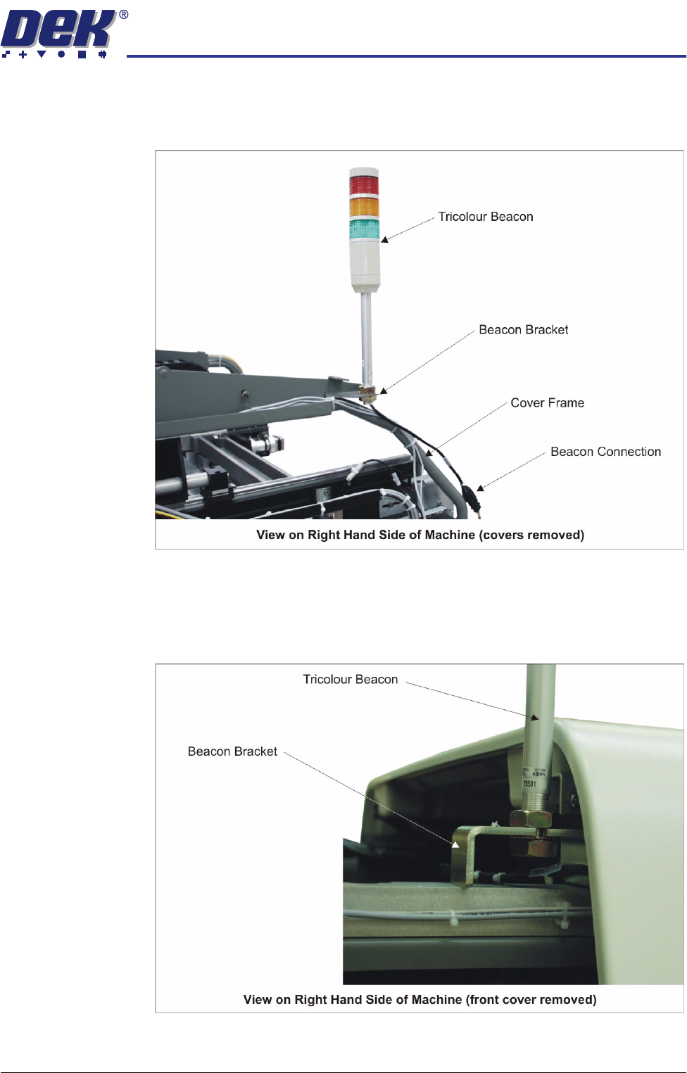
Machine Assembly Assemble the following machine components and assemblies:
Tricolour Beacon
(Sliding Glass Cover
Design)
1. Fit the tricolour beacon to the beacon bracket ensuring that the cable is not
trapped between the beacon and the cover frame.
2. Connect the tricolour beacon connection 14PL07 to 14SK07.
3. Cable tie the loose cable to the cover frame.
Tricolour Beacon
(Gull Wing and
Shutter Cover
Design)
1. Fit the tricolour beacon to the beacon bracket ensuring that the cable is not
trapped between the beacon and the cover frame.
2. Connect the tricolour beacon connection 14PL07 to 14SK07.
3. Cable tie the loose cable to the cover frame.