Printer 710_810 v8 Transportation.pdf - 第89页
TRANS PORTATION MAJOR RELO CATION Chapter Issue 7 Oct 06 Technical Reference Manual 34.89 ProFlow 1. Carefull y positi on the ProFlow p rinthead mechani sm so that bot h locating dowels locate into the print car riage lo…
TRANSPORTATION
MAJOR RELOCATION
34.88 Technical Reference Manual Chapter Issue 7 Oct 06
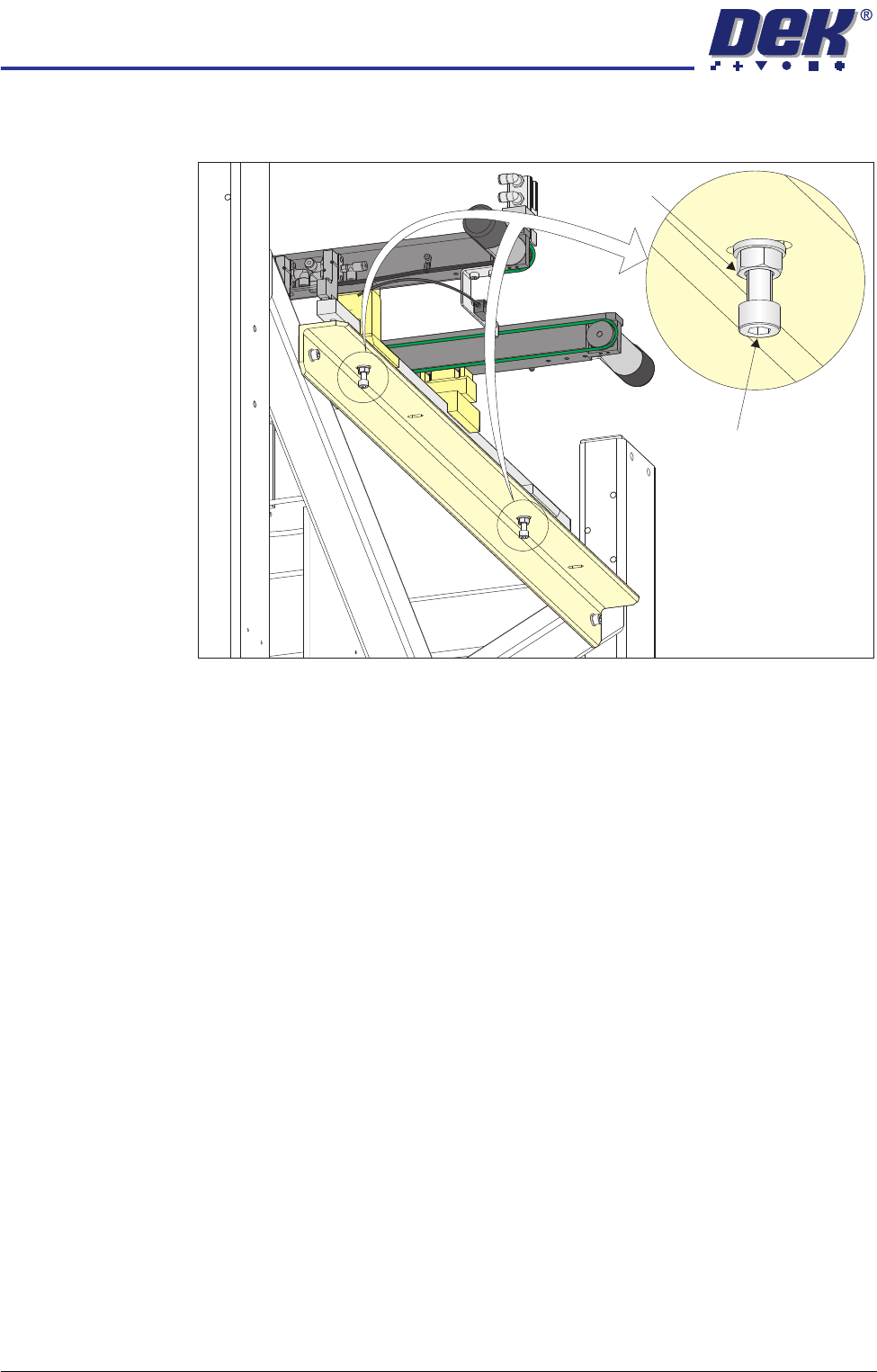
5. If adjustment is required, loosen the two locknuts on the auxiliary conveyor
height adjustment bolts.
6. To alter the height of the conveyor carefully adjust both height adjustment
bolts.
7. Carefully adjust the height of the conveyor rails until they match the print
station rails.
8. Re-tighten the locknuts loosened in Step 5 and repeat the check.
9. If adjustment has occurred, carry out Auxiliary Conveyor Levelling check.
10. Fit the side covers and panels that were previously removed.
Auxiliary Conveyor
Height Adjustment
Bolt
Locking Nut
TRANSPORTATION
MAJOR RELOCATION
Chapter Issue 7 Oct 06 Technical Reference Manual 34.89
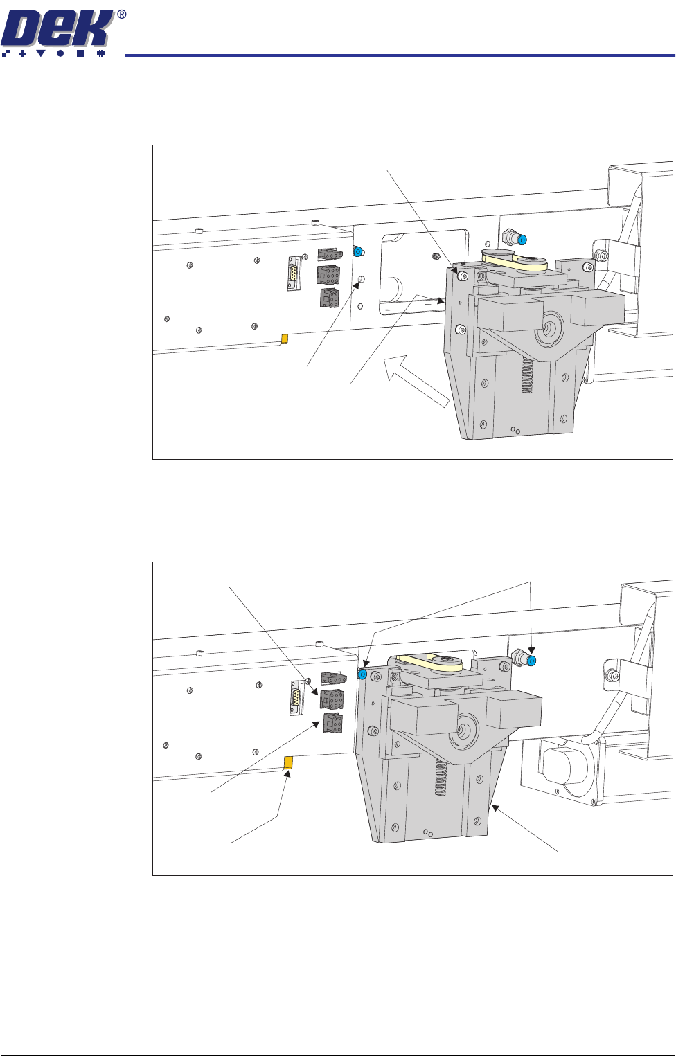
ProFlow 1. Carefully position the ProFlow printhead mechanism so that both locating
dowels locate into the print carriage locating holes. Secure the unit to the
print carriage by means of the four captive screws.
2. Connect the following connectors to the print carriage, left hand side:
• ProFlow motor connector 9PL17 into 9 way socket 9SK17
• ProFlow home sensor connector 9PL08 into 6 way socket 9SK08
Captive Screw (in 4 positions)
Locating Dowel
(in 2 positions)
Print Carriage Locating
Hole (in 2 positions)
Pneumatic Connectors
ProFlow Motor
(9SK17)
Home Sensor
(9SK08)
ProFlow Paste Level
Sensor (9PL61)
ProFlow Printhead
Mechanism
TRANSPORTATION
MAJOR RELOCATION
34.90 Technical Reference Manual Chapter Issue 7 Oct 06
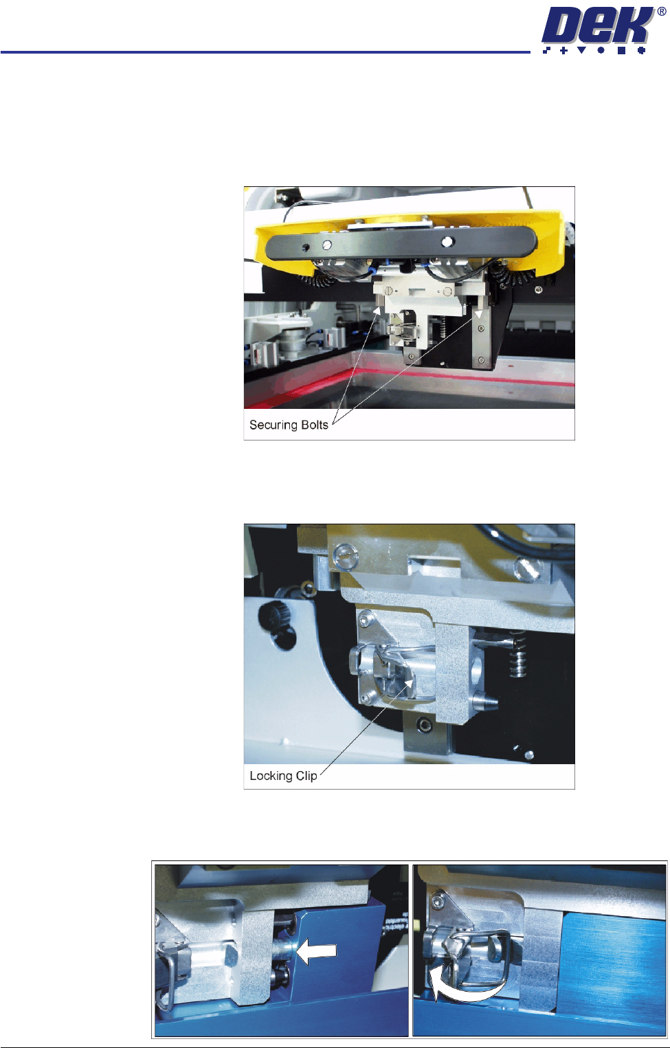
3. Fit the pressure mechanism part of the ProFlow unit to the ProFlow print-
head mechanism bearing block by means of the two securing bolts. Tighten
using a 5mm Allen key.
NOTE
Unit shown in unlatched position to identify bolts.
4. Ensure that the locking clip on the pressure mechanism is pressed over to
the right and clicks into place, as shown in the figure below. This ensures
that the locking clip is in the correct position to secure the transfer head.
5. Locate and fit the ProFlow transfer head unit to the pressure mechanism by
means of the two locating dowels. Slide the unit onto the pressure mecha-
nism. Once the unit is slid fully home, it is secured by closing the locking clip.