Printer 710_810 v8 Transportation.pdf - 第96页
TRANSPORT ATION PRE POWER UP CHECKS 34.96 Technical Reference Manual Chapter Issue 7 Oct 06 External Servi ces In order for the machine to functi on correctly the fol lowing services must be availabl e: • Pneumatic Suppl…
TRANSPORTATION
PRE POWER UP CHECKS
Chapter Issue 7 Oct 06 Technical Reference Manual 34.95
Vacuum Filtration
Unit
There are three types of onboard vacuum filtration unit, for use with the under
screen cleaner, the VF25, the VF10 and the VF35i. The VF25 is a fixed voltage
unit at either 110V or 230V, ensure that the unit fitted matches the supply
voltage.
The onboard VF35i vacuum filtration unit is dual voltage 110V/230V (50Hz/
60Hz) switchable from the front panel of the unit.
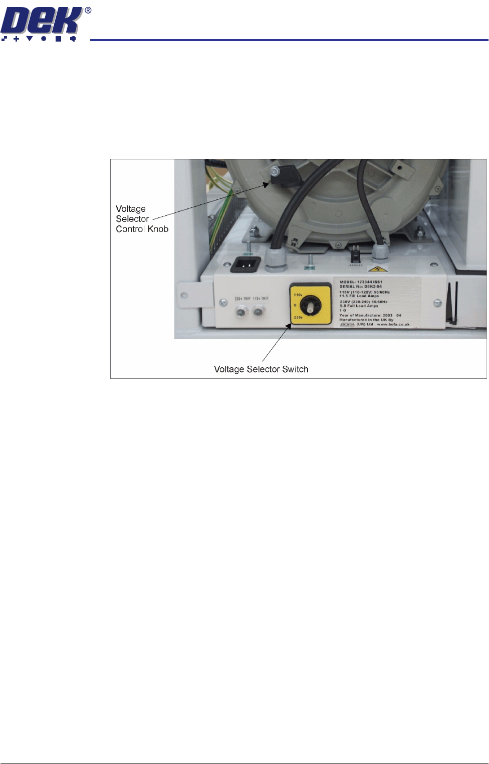
Figure 34-25 Vacuum Filtration Unit
Ensure that the voltage selector switch, on the front panel of the onboard
vacuum filtration unit, is set to match the supply voltage. To check or switch the
voltage selector, carry out the following:
1. Using a 10mm spanner, remove the voltage selector control knob from the
fan housing.
2. Fit the voltage selector control knob to the voltage selector switch.
NOTE
The spindle has three keyways allowing the knob to be fitted in one position
only.
3. Ensure that the pointer of the knob is indicating the voltage that closely
matches the mains supply voltage.
CAUTION
VACUUM FILTRATION UNIT.
This unit is liable to damage if the voltage
selector does not match the supply voltage.
NOTE
The ‘0’ position on the voltage selector is OFF disabling the vacuum filtration
unit.
4. Return the voltage selector control knob to the fan housing to prevent further
adjustment.
TRANSPORTATION
PRE POWER UP CHECKS
34.96 Technical Reference Manual Chapter Issue 7 Oct 06
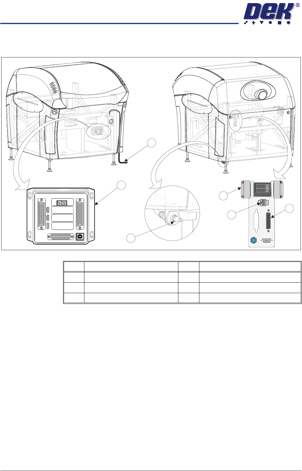
External Services
In order for the machine to function correctly the following services must be
available:
• Pneumatic Supply
• Electrical Supply
Other services that may be required are:
• Host Communications
• Upline/Downline Machine Interface (FMI/MIU)
• Temperature Control Module (TCM)
Item Description Item Description
1 Printer Mains Supply Cable 4 Foreign Machine Interface (FMI) Pod
2 Temperature Control Module (TCM) 5 Air Connection
3 Host Comms LAN RJ45 6 Multi Interface Unit (MIU)
M
1S
K1
M1SK1
U
PL
IN
E
UPLI
NE
M
1
SK
2
M1SK2
D
O
W
N
L
I
N
E
DO
W
NLINE
M
1
P
L3
M
1PL3
DE
K
M
/C
DEK
M/C
M
1
S
K
4
M
1S
K
4
D
EK
US
B
DE
K
USB
+1
2
V
+12V
+24
V
+24V
+2
4V
S
W
+24V
SW
S
EN
D
U
PL
IN
E
SE
ND
UP
LI
N
E
SE
ND
D
OW
NL
I
N
E
S
E
ND
D
OWN
L
I
N
E
C
ON
T
R
OL
I
N
CO
NTR
OLI
N
U
PLI
NE
R
EA
D
Y
UPL
I
NE
READ
Y
DO
W
N
LIN
E
RE
A
D
Y
DOWNLINE
READY
CO
NT
R
O
L
O
UT
C
ON
TROLOUT
P
O
W
E
R
PO
W
ER
I/P'
S
I/P'
S
O
/
P
'
SO
/
P
'
S
P
R
O
T
O
C
OL
S
EL
E
C
T
I
O
N
P
R
O
T
O
C
OLSELE
C
TIO
N
U
P
UP
L
IN
E
LI
NE
D
OW
N
DOWN
L
IN
E
LI
N
E
M
IU
1
9
1
11
4MIU
191114
4
8
0
4
8
0
POWER ON
PART No. 160740
M/C AVAILABLE
BOARD AVAILABLE
BOARD PASS
D
O
W
N
LIN
E
BOARD AVAILABLE
BOARD PASS
M/C AVAILABLE
U
P
LIN
E
FMI POD
View on RearView on Front
1
2
3
4
5
6
M1SK1
UPLINE
M1SK2
DOWNLINE
M1PL3
DEK M/C
M1SK4
DEK USB
+12V
+24V
+24V SW
SEND UPLINE
SEND DOWNLINE
CONTROL IN
UPLINE READY
DOWNLINE READY
CONTROL OUT
POWER
I/P'S
O/P'S
PROTOCOL SELECTION
UP
LINE
DOWN
LINE
MIU 191114
4
80
4
80
TRANSPORTATION
PRE POWER UP CHECKS
Chapter Issue 7 Oct 06 Technical Reference Manual 34.97
Pneumatic Supply The machine requires a pneumatic supply of clean, non lubricated air which
should maintain a minimum pressure 5 Bar and a maximum of 8 Bar.
The air should be to ISO 8573.1 standard, quality class 2.3.3, where:
• 2 dirt = 1 micron
• 3 water = -20°C pressure dewpoint
• 3 oil = 1mg/m3
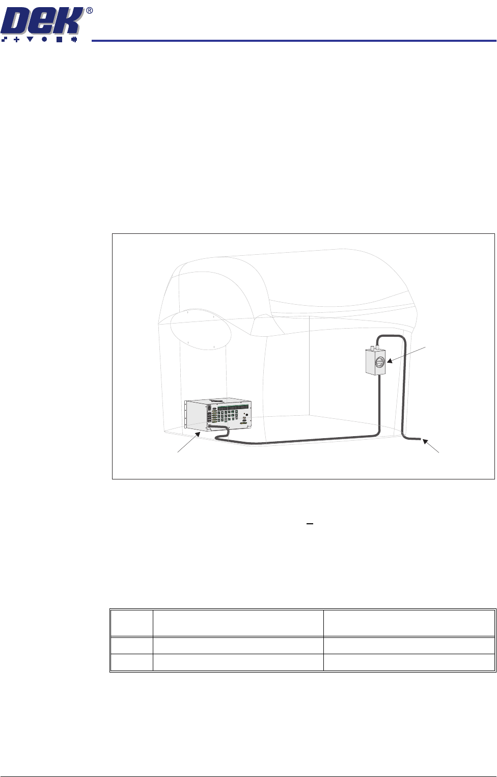
Electrical Supply The factory mains supply for the machine is routed through the front panel
mounted mains isolator switch and on to the M37 power supply enclosure where
various low voltages are distributed throughout the machine.
Figure 34-26 Mains Electrical Supply
The machine operates on 100V to 240V +
10% 50/60Hz single phase ac mains.
DEK recommends a power supply capacity of 2.4KVA or greater.
DEK requires additional machine supply protection with the fitment of an
external double pole circuit breaker conforming to national, federal or local
legislation. Use the following table to ensure the recommended circuit breaker
is used:
CAUTION
OVER CURRENT PROTECTION.
An over current circuit breaker protects the
machines internal wiring and components from overheating or catching
fire during fault conditions. Under no circumstances must a circuit
breaker of value greater than 25 Amps be fitted.
Voltage Value of Wall Mounted Circuit Breaker
(without Internal Vacuum Unit)
Value of Wall Mounted Circuit Breaker
(with Internal Vacuum Unit)
115V 10 Amp 25 Amp
230V 4/6 Amp 13/16 Amp
To Factory Mains Supply
Mains Isolator
Switch
M37 Power Supply Enclosure