80S-2080F480F5.pdf - 第101页
SIPLACE 80S-20/F4/F5 User M anual 2 Introduction and Basic Concepts 05/99 Issue from Software Version SR.405.xx 2.2 Principles and Structure of the User Interface 2 - 17 2.2.3. 2 Input B oxes Input box es requ ire of th …
2 Introduction and Basic Concepts SIPLACE 80S-20/F4/F5 User Manual
2.2 Principles and Structure of the User Interface 05/99 Issue from Software Version SR.405.xx
2 - 16
2.2.3 Screen Displays
Once menus have been selected and actions executed, various messages and input fields may appear.
These are explained in more details in the following text.
In the following user’s manual, the finger in the screen menus indicates where actions are to be car-
ried out or inputs are to be made.
NOTE
Message boxes, input boxes and the like can be shifted on the screen to allow hidden text to be read.
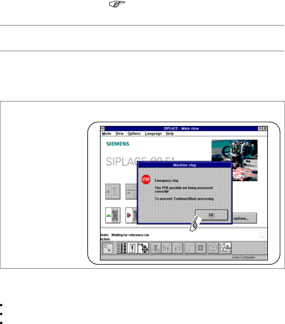
2.2.3.1 Warning and Message Boxes
Fig. 2.2.6 Example of warning and message box
Warning and message boxes show which action has been carried out with the machine and which action is
required of the operator.
Read and comply with the message in the warning and message box.
Click on the OK button.
Carry out the action which you have been asked to perform.
SIPLACE 80S-20/F4/F5 User Manual 2 Introduction and Basic Concepts
05/99 Issue from Software Version SR.405.xx 2.2 Principles and Structure of the User Interface
2 - 17
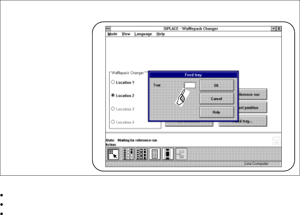
2.2.3.2 Input Boxes
Input boxes require of the operator that he make an entry in the input field.
Fig. 2.2.7 Example of input box
Position the cursor within the input field.
Type into the input field the input which is required.
Confirm your input by clicking on
OK
. You can break off your input by clicking on the
Cancel
button or you
can call up on-line help on the corresponding topic by clicking on the
Help
button (see also Chapter 8).
2 Introduction and Basic Concepts SIPLACE 80S-20/F4/F5 User Manual
2.2 Principles and Structure of the User Interface 05/99 Issue from Software Version SR.405.xx
2 - 18
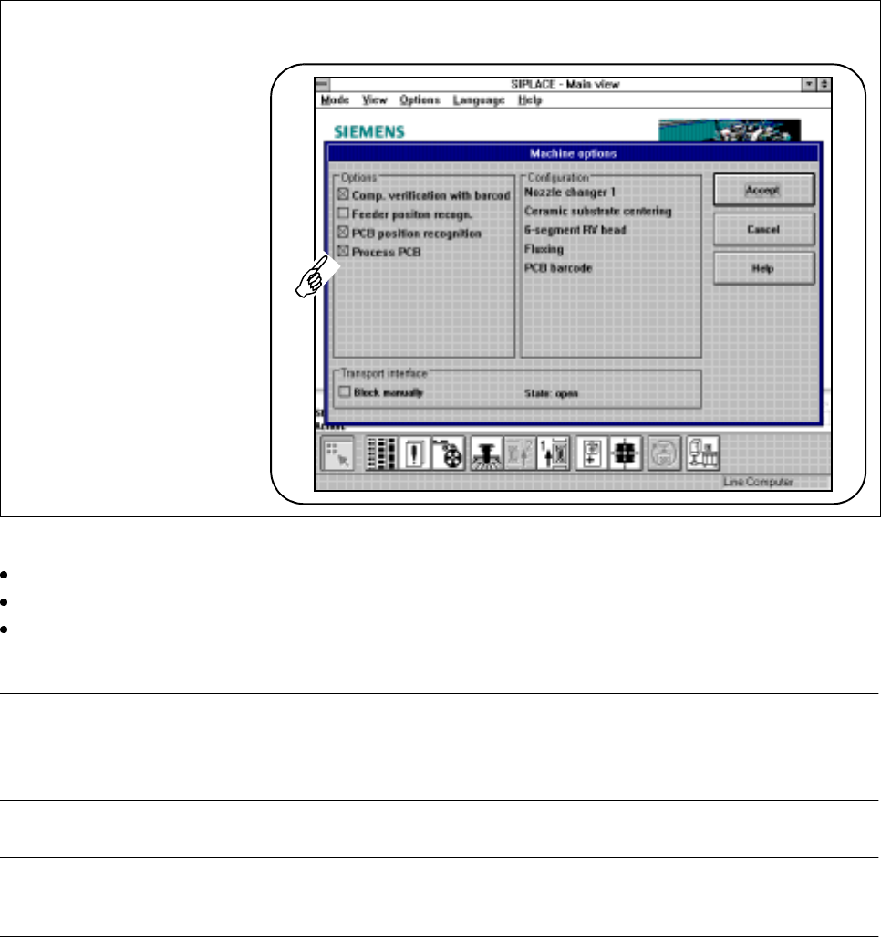
2.2.3.3 Control Boxes
Control boxes display states and settings which can be activated or deactivated.
Fig. 2.2.8 Example of a control box
Click on a control button in the control box in order to activate or deactivate a displayed state or setting.
Click on the
Accept
button in order to activate the processed states or settings.
You can break off your input by clicking on the
Cancel
button (the old settings will be used) or you can call
up on-line help on the corresponding topic by clicking on the
Help
button (see also Chapter 8).
NOTE
A cross on a control button indicates an activated state.
An empty control button indicates a deactivated state.
PLEASE NOTE
Some operations (e.g. machine options for line engineers) can only be accessed from a higher operator level.