80S-2080F480F5.pdf - 第94页
2 Introduction and Ba sic Concepts SIPLACE 80S-20/F4/F5 User Manual 2.1 Display and Controls on the Machine 05/99 Issue from Software V ersion SR.405.xx 2 - 10 2.1.7 Main Fault Indicator For each gantry there is a fa ult…
SIPLACE 80S-20/F4/F5 User Manual 2 Introduction and Basic Concepts
05/99 Issue from Software Version SR.405.xx 2.1 Display and Controls on the Machine
2 - 9
2.1.6 Switches on the Machine
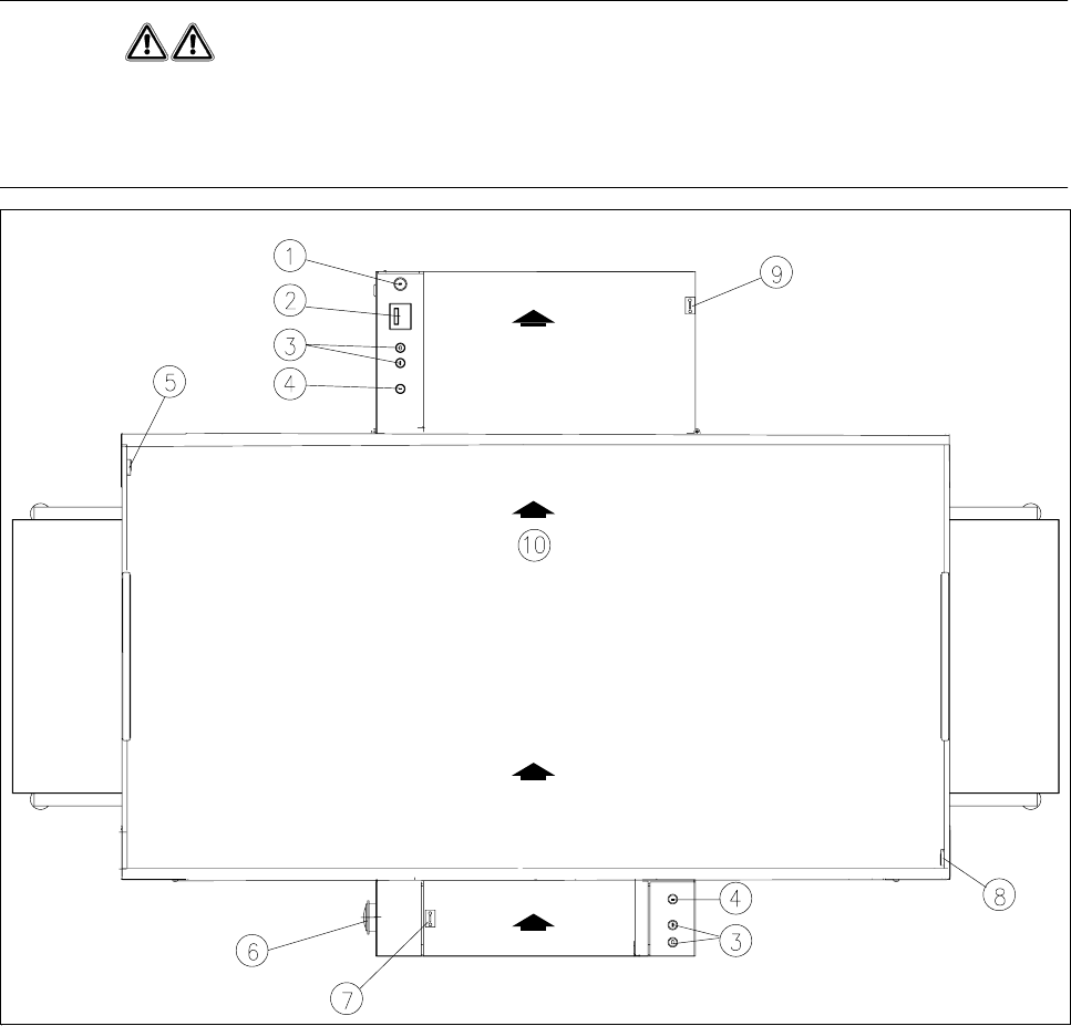
Fig. 2.1.5 shows the position on the machine of the main switch, the cover switch, pushbuttons for start and
stop, the EMERGENCY STOP mushroom-head push-button, and the key-operated switch.
WARNING
Only appropriately qualified personnel are permitted to use the key-operated switch for servicing or mainte-
nance work. In all other cases the key must be kept secure against unauthorized access as otherwise the out-
come could be serious injury to the person or damage to the machine.
Fig. 2.1.5 Position of the switches on the machine
- Key to Fig. 2.1.5
1 Key-operated switch 2 Components counter
3 Start and stop buttons 4 Emergency stop mushroom-head push-button
5 Left cover switch 6 Main switch
7 Cover switch on cover of input belt 8 Right cover switch
9 Cover switch on cover of output belt 10 Transport direction
2 Introduction and Basic Concepts SIPLACE 80S-20/F4/F5 User Manual
2.1 Display and Controls on the Machine 05/99 Issue from Software Version SR.405.xx
2 - 10
2.1.7 Main Fault Indicator
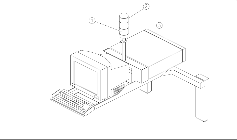
For each gantry there is a fault indicator light on the main fault indicator. The lower fault indicator light is for
gantry 1 and the top indicator light is for gantry 2.
Fig. 2.1.6 Main fault indicator
- Key to Fig. 2.1.6
1 Fault indicator lamp (white), gantry 1 (location 3/4) 2 Fault indicator lamp (white), gantry 2 (location 1/2)
3 Operating status lamp (green)
2.1.7.1 Functional Description
- Operating status lamp lights up continuously
The placement system is in service
- Operating status lamp flashes
The placement system is either waiting for a PCB on the input conveyor or is waiting until the output con-
veyor becomes free.
- The fault light flashes
One or more tracks of the gantry in question are empty. The machine will however work its way through the
remaining components.
- The fault light is continuously illuminated
A fault has occurred in the gantry in question. The machine has stopped.
- Both fault lights are continuously illuminated.
A fault has occurred affecting the entire machine. The machine has stopped.
SIPLACE 80S-20/F4/F5 User Manual 2 Introduction and Basic Concepts
05/99 Issue from Software Version SR.405.xx 2.2 Principles and Structure of the User Interface
2 - 11
2.2 Principles and Structure of the User Interface
The menu guidance system and the appearance of the user interface for the SIPLACE 80S-20/F
4
//F
5
use
MS Windows and are based on the MS Windows NT 4.0 standard.
2.2.1 Working with the Trackball and Touch Screen
The trackball with its mouse buttons is integrated into the keyboard (see Fig. 2.1.2).
The trackball is used to move the mouse pointer over the screen onto the menus, menu names, icons (but-
tons) or selector fields, which can then be selected or activated with the lefthand mouse button. Another way
of doing this is to touch the screen (touch screen) directly with your fingertip to select or activate functions. In
the sections which follow these actions are described as ’clicking’.
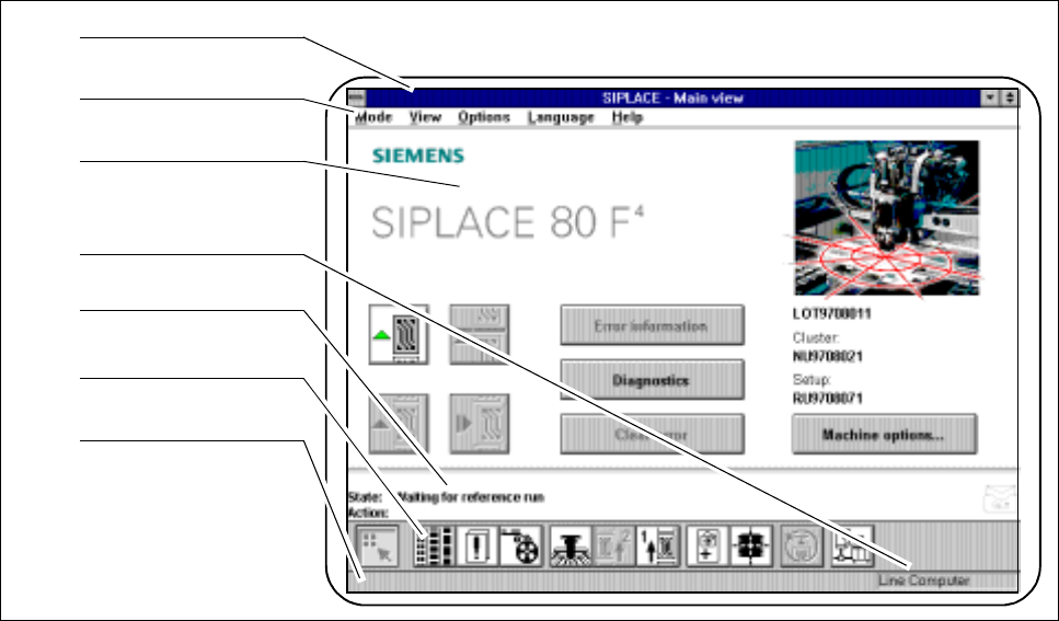
2.2.2 Organization of the Screen
Fig. 2.2.1 Organization of the screen
- Key to Fig. 2.2.1
1 Menu line 2 Title bar
3 Working or client area 4 Machine control mode
5 Status window 6 Symbol strip
7 Status line
1
2
3
4
5
6
7