80S-2080F480F5.pdf - 第417页
SIPLACE 80S-20/F4/F5 User M anual 6 What should you d o ... ? 05/99 Issue from Software Version SR.405.xx 6.4 When you change shift 6 - 9 6.4 When you chan ge shift Splice t he tapes in go od time so that th e feeder m o…

6 What should you do ... ? SIPLACE 80S-20/F4/F5 User Manual
6.3 When you change the job 05/99 Issue from Software Version SR.405.xx
6 - 8
6.3 When you change the job
Stop the placement program at the line computer (job control: red lamp).
Specify the new placement program.
Check the width of the conveyor belt.
Check the position of the magnetic supports and make sure that they cannot collide with components on
the bottom of the PCB.
Carry out the set-up check.
Check that the feeder modules are equipped with the correct components and that they are at the correct
locations.
Check the nozzle configuration.
If no nozzle changer is installed, you must change the nozzles manually.
PLEASE NOTE:
If you change the nozzle manually, ALWAYS ensure that the nozzle is seated correctly and that you are
using the correct nozzle type.
If you have not inserted a nozzle or have used the wrong nozzle type, the program will prompt you to move
the placement head to the service position and change the nozzle. This error message will also appear if
you have not inserted the nozzle correctly.
If you insert the wrong nozzle or use the wrong nozzle type again, the gantry will move to the service posi-
tion once more after the reference sequence. The program will continue to prompt for a nozzle change
until you have obtained the correct configuration. If you do not succeed then proceed as follows:
– Switch off the station and cancel the program being sent to the station at the line computer.
– Rectify the nozzle error and restart the station.
TIP
Have the nozzles ready in a separate nozzle box - identify each compartment with the nozzle type and
color. This will prevent any confusion.
Do not raise used plastic nozzles. Just dispose of them immediately.
Fig. 6.3.1 Nozzle box
701
yellow
704
orange
705
red
711
yellow

SIPLACE 80S-20/F4/F5 User Manual 6 What should you do ... ?
05/99 Issue from Software Version SR.405.xx 6.4 When you change shift
6 - 9
6.4 When you change shift
Splice the tapes in good time so that the feeder modules will not run out of tape as soon as the new shift
starts. This can sometimes lead to pick-up errors and prolonged down-times.
Pass on information from one shift to the next if, for example, something has been changed in the place-
ment program or if frequent errors have occurred in certain feeder modules. Also take a look at the ’Feeder
module preliminary setup area' checklist in section 6.6, pages 6-12.
Carry out a set-up check.
Check that the feeder modules are equipped with the correct components and that they are at the correct
locations.
TIP
When you hand over the line, make sure that it as you would want to find it yourself, i.e. that
- The reject containers are empty.
- The waste containers are empty.
- The conveyor areas have been cleaned with a vacuum cleaner.
- Defective feeder modules in the feeder area have been replaced.
6 What should you do ... ? SIPLACE 80S-20/F4/F5 User Manual
6.5 When you, as an operator, carry out a walk-round inspection 05/99 Issue from Software Version SR.405.xx
6 - 10
6.5 When you, as an operator, carry out a walk-round
inspection
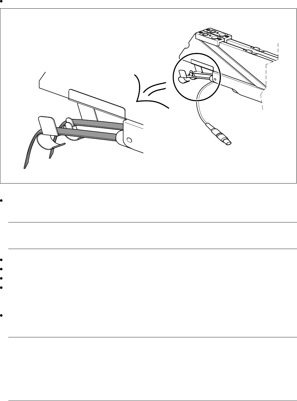
Check that the tape is lying correctly in the springs of the 8 mm S.
Fig. 6.5.1 Placing the tape in the springs of the 8 mm S
Check whether the tape cover foil container for the 8 mm S is full. If it is, pull out the foil and cut it off with
scissors.
PLEASE NOTE:
If you tear the foil, this can lead to tape removal problems.
Check whether the window on the feeder module is the right size for the component.
Are the tape guides used on the feeder modules intended for different tape widths?
Is the additional plastic guide in use for tapes of different widths?
Check the position of the stopper on the PCB transport.
Always position the stopper centrally, outside the PCB. Make sure that the stopper is also positioned out-
side any recesses in the PCB.
Check the magnetic supports on the lifting table. They must be arranged so that they do not collide with
components on the bottom of the PCBs.
PLEASE NOTE:
Splice the tapes in good time so that the feeder modules will not run out of tape, since this will increase
the frequency of stoppages.
However, do not splice the tapes too early since, if you wind the end of the old tape onto the new reel after
splicing, the reel holding the new tape will be overfilled and the tapes will slip off the reel and become tan-
gled up. This will again result in pick-up errors and more stoppages.