80S-2080F480F5.pdf - 第404页
5 Vision Functions SIP LACE 80S-20/F4/F5 Us er Manual 5.11 Coplanarity Laser Module (SIPLACE 80F4 or 80F5 only) 05/99 Issue from Software Version SR.405.xx 5 - 172 Line en gineer Fig. 5.1 1.5 Cop lanarity laser module - …
SIPLACE 80S-20/F4/F5 User Manual 5 Vision Functions
05/99 Issue from Software Version SR.405.xx 5.11 Coplanarity Laser Module (SIPLACE 80F4 or 80F5 only)
Line engineer 5 - 171
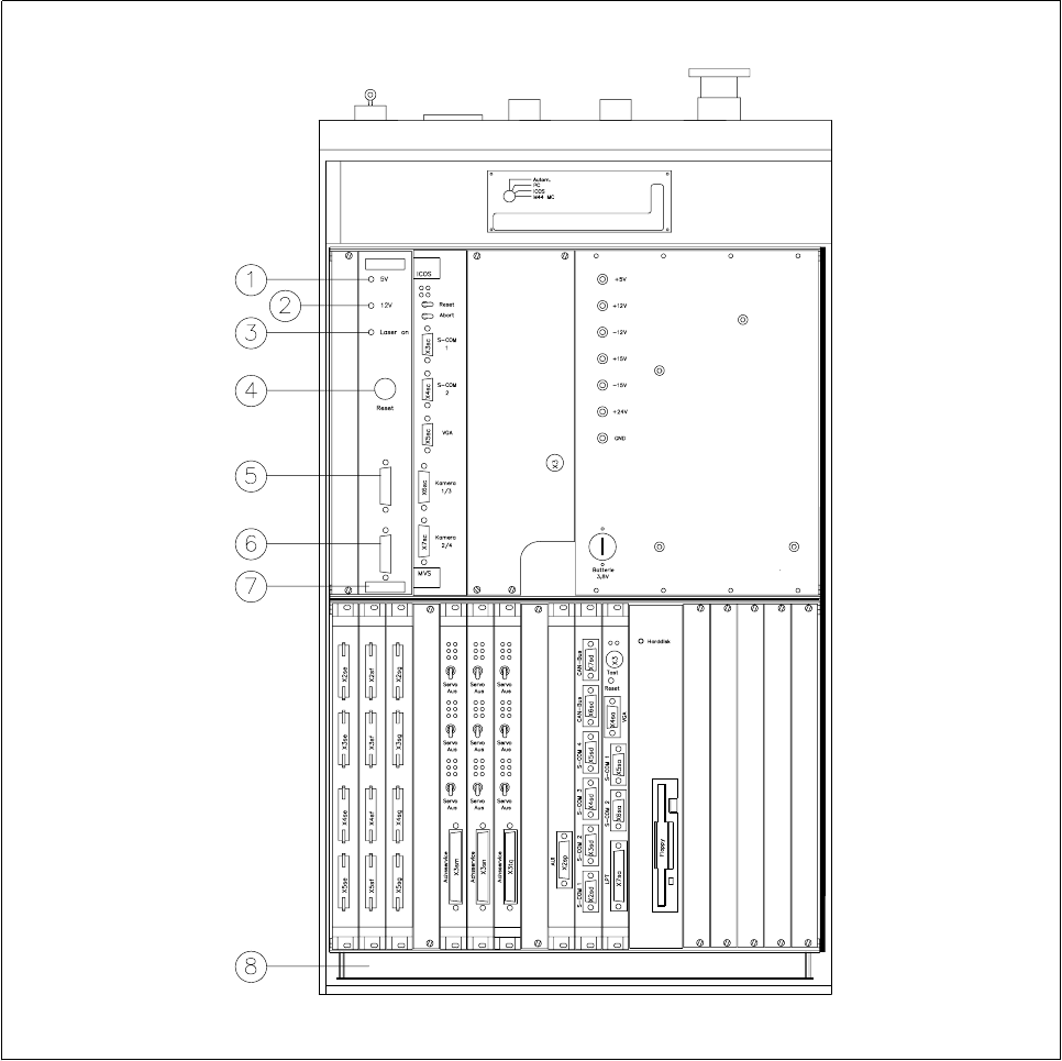
Fig. 5.11.4 Overview of the coplanarity laser module
- Key to Fig. 5.11.4
1 Green LED: Operating voltage 5V
2 Green LED: Operating voltage 12V
3 Green LED: Laser module switched on
4 RESET key
5 SUB-D plug, 9-pin, COM2: to the machine controller
6 SUB-D plug, 15-pin: to the laser module
7 Analysis unit with control section
8 Control unit 80F
4
5 Vision Functions SIPLACE 80S-20/F4/F5 User Manual
5.11 Coplanarity Laser Module (SIPLACE 80F4 or 80F5 only) 05/99 Issue from Software Version SR.405.xx
5 - 172 Line engineer
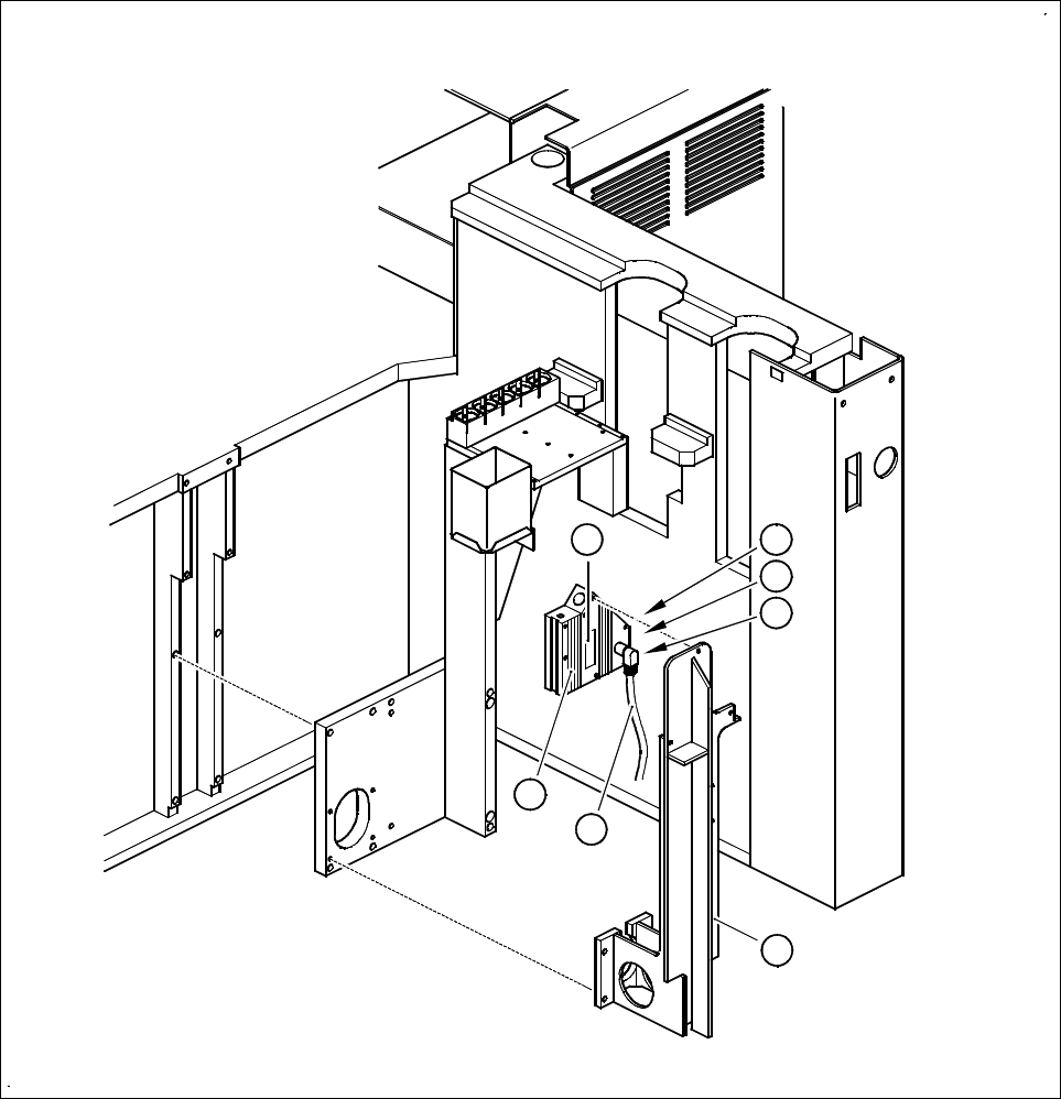
Fig. 5.11.5 Coplanarity laser module
- Key to Fig. 5.11.5
1 Laser module
2 Connecting cable
3 Supporting frame
4 Red LED: OUT OF RANGE
5 Red LED: POOR TARGET
6 Green LED: LASER ON
7 Label ’laser class 3B’, see Fig. 5.11.2
4
5
6
1
2
3
7

SIPLACE 80S-20/F4/F5 User Manual 5 Vision Functions
05/99 Issue from Software Version SR.405.xx 5.11 Coplanarity Laser Module (SIPLACE 80F4 or 80F5 only)
Line engineer 5 - 173
5.11.5 Entering Data
– Coplanarity measurement must have been added, via the GF editor, to the
Handling rules
. (See Section
5.4.4 of the SIPLACE UNIX line computer user’s manual).
– Add the maximum coplanarity deviation (see
Max. component height tolerance
in Section 5.2.5
Func-
tion of the Cluster Editor
of the SIPLACE UNIX line computer user’s manual).
NOTE
In the
Placement options
menu (see Section 5.3 of this user’s manual) you can deactivate or activate the
coplanarity laser module. Coplanarity measurement can be switched on or off for all of those components for
which coplanarity measurement has been set in the package form data.
r