80S-2080F480F5.pdf - 第392页
5 Vision Functions SIP LACE 80S-20/F4/F5 Us er Manual 5.8 Recommendation for vis ually centering components 05/99 Issue from Software V ersion SR.405.xx 5 - 160 Line en gineer 5.8.4 Visuall y centering flip-chip s 5.8.4.…

SIPLACE 80S-20/F4/F5 User Manual 5 Vision Functions
05/99 Issue from Software Version SR.405.xx 5.8 Recommendation for visually centering components
Line engineer 5 - 159
5.8.2.4 Optimizing multiple measurements for screening plates
Screening plates that are larger than 32 mm x 32 mm are generally visually centered by multiple measure-
ment, although single measurement can still be used if you select a section of the component which is less
than 32 mm x 32 mm. To do this, select a characteristic, non-repeated ball pattern in order to avoid incorrect
placement.
Enter a value < 32 mm x 32 mm for the length and width of the component under the ’Case dimension’
option in the ’Test component’ menu.
5.8.3 General recommendations for centering flip-chips, BGAs and
screening plates
5.8.3.1 Setting the ball contrast parameters
If you select a high value for the ’Ball image’ option in the ’Test component’ menu, this will reduce the effect of
any defective structures. It does mean, however, that there is a possibility that not every ball will be detected.
Set a lower value to ensure that all the balls are detected. This will reduce the reject rate, but the measure-
ment will take longer.
5.8.3.2 Setting the ball radius parameters
Enter the ball radius on the line computer. This value is automatically reduced by 20 % since the vision sys-
tem will detect balls even if the specified dimensions are smaller then their actual physical dimensions.
So, set the ball radius on the station computer and then adjust the quality in the ’Measure’ menu.
– If no crosses are displayed on the ball, the radius is incorrect or the contrast is too high.
– If several crosses are displayed on a ball, then the radius has been entered incorrectly in the ’Measure’
menu.
PLEASE NOTE:
We recommend that you select a radius on the line computer that is slightly larger than the theoretical value
and then adjust it in the ’Ball image’ menu.
5.8.3.3 Setting the case shape dimension parameters on the station computer
For high-contrast flip-chips and BGAs, you can reduce the physical case shape dimension to the square sur-
rounding the balls (’Case dimension’ option). This will reduce the measuring time, although it can only be used
for single measurements. Size mode must also be active.

5 Vision Functions SIPLACE 80S-20/F4/F5 User Manual
5.8 Recommendation for visually centering components 05/99 Issue from Software Version SR.405.xx
5 - 160 Line engineer
5.8.4 Visually centering flip-chips
5.8.4.1 Setting the parameters on the station computer
Under the ’Illumination’ option in the ’Test component’ menu, select:
– a value of around 50 for the medium illumination plane
– a value of around 20 for the steep illumination plane
5.8.4.2 Recommended sequence of measurements for visually centering bare dies
Measuring mode Size Grid Ball
Settings
Resolution in the measuring direction:
very high
——
Resolution in the integration direction:
very high
——
Tab. 5.8.3 Recommended sequence of measurements for visually centering bare dies
SIPLACE 80S-20/F4/F5 User Manual 5 Vision Functions
05/99 Issue from Software Version SR.405.xx 5.9 Teach Fiducial: Additions with the 80F4 or 80F5 Machines
Line engineer 5 - 161
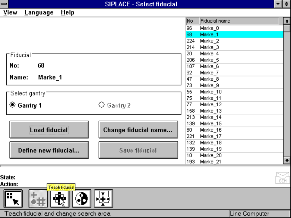
5.9
Teach Fiducial
: Additions with the 80F
4
or 80F
5
Machines
In contrast to the 80S-20 placement machine the 80F
4
or 80F
5
machine is a single-gantry machine. For this
reason in the
Teach fiducial
menu the
Select gantry
option is permanently set to
Gantry 1
. The
Gantry 2
option cannot be clicked on.
The IC placement head is mounted on the gantry, together with the 12x revolver placement head on the 80F
4
and the 6x revolver placement head on the 80F
5
automatic placement machines. The camera system for
board centering is accommodated on the gantry underside.
All menus with the exception of this option are identical to those of the 80S-20 machine.
A description of the menus and their options will be found in Section 5.5 from Page 5 - 37.
Fig. 5.9.1
Select fiducial
menu,
Select gantry
option