80S-2080F480F5.pdf - 第239页
SIPLACE 80S-20/F4/F5 User M anual 5 Vision Func tions 05/99 Issue from Software Vers ion SR.405.xx 5.1 Overview of the Vision S ystems in the SIPLACE 80S-20 /F4F5 Machines Line en gineer 5 - 7 Fig. 5.1.4 Vision evaluatio…
5 Vision Functions SIPLACE 80S-20/F4/F5 User Manual
5.1 Overview of the Vision Systems in the SIPLACE 80S-20/F4F5 Machines 05/99 Issue from Software Version SR.405.xx
5 - 6 Line engineer
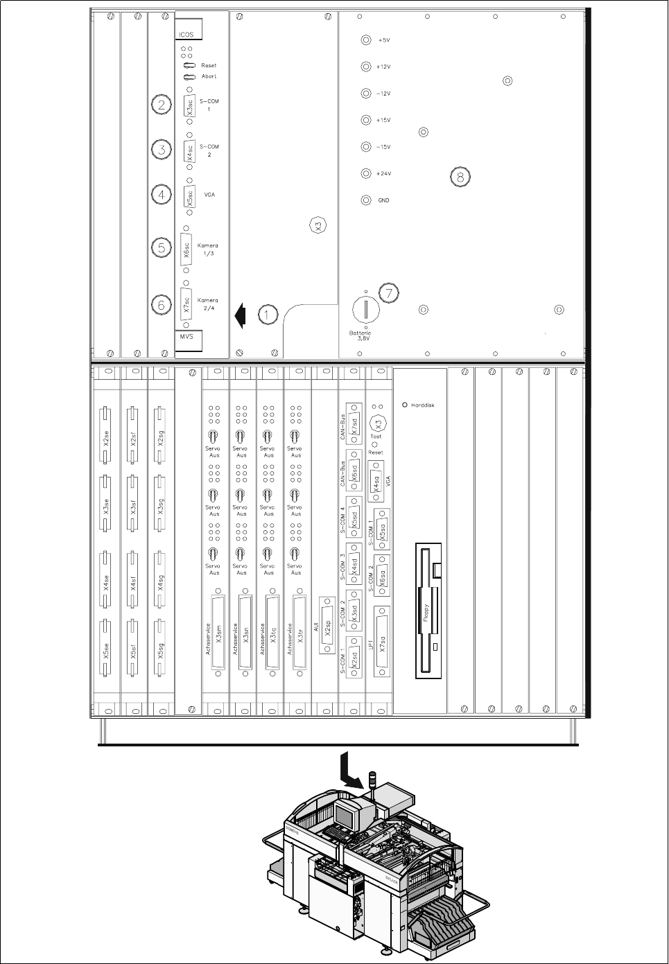
The control unit of the machine accommodates an evaluation unit (ICOS MVS system) (5 - 7) which pro-
cesses and quantifies the signals from the camera systems (PCB and component vision systems) of each
placement head. The deviations from the nominal values are used for determining correction values which are
then used in the recalculation of the placement positions and the skew of the components to be inserted.
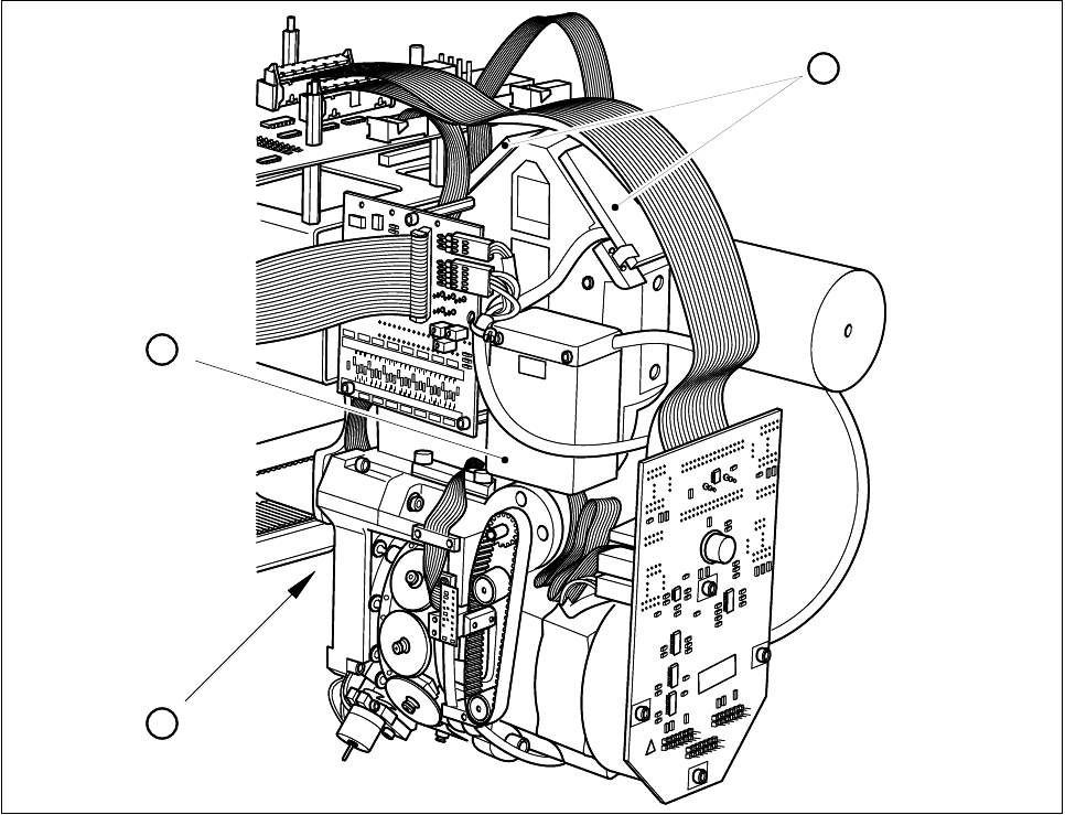
Fig. 5.1.3 Camera systems for PCB and component position recognition at the 12x revolver heads
- Key to Fig. 5.1.3
1 Deflection mirror and component lens 2 Component camera amplifier
3 PCB camera on the underside of the gantry
- Key to Fig. 5.1.4
1 PCB and component evaluation unit of vision system 2 COM1
3 COM2 4 Monitor connection
5 Camera connections 6 Camera connections
1 PCB camera, gantry 1 2 PCB camera, gantry 2
3 Component camera, gantry 1 4 Component camera, gantry 2
7 Battery 8 Power supply unit
008
008
2
3
1
008
008
2
3
1
SIPLACE 80S-20/F4/F5 User Manual 5 Vision Functions
05/99 Issue from Software Version SR.405.xx 5.1 Overview of the Vision Systems in the SIPLACE 80S-20/F4F5 Machines
Line engineer 5 - 7
Fig. 5.1.4 Vision evaluation unit for gantries 1 and 2 of the SIPLACE 80S-20 machines
5 Vision Functions SIPLACE 80S-20/F4/F5 User Manual
5.1 Overview of the Vision Systems in the SIPLACE 80S-20/F4F5 Machines 05/99 Issue from Software Version SR.405.xx
5 - 8 Line engineer
5.1.2 Vision Systems in the SIPLACE 80F
4
Placement Machine
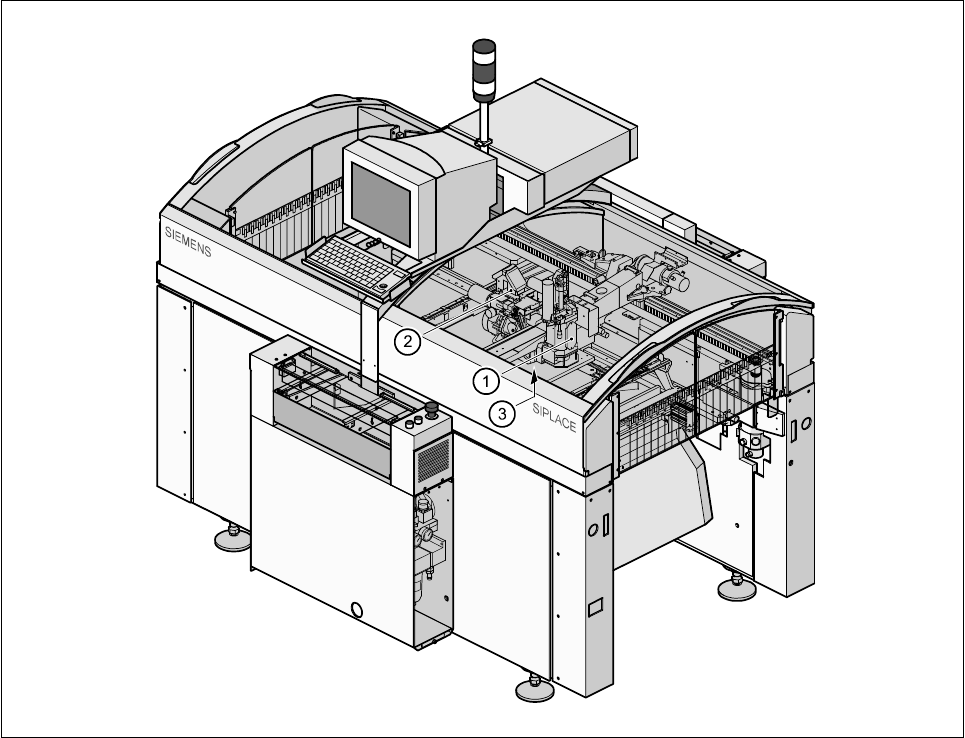
The single gantry system of the SIPLACE 80F
4
machine (5 - 8) is fitted with one revolver placement head and
one IC placement head. The revolver placement head is equipped with a camera system for component posi-
tion recognition (5 - 6). The camera systems (up to two) for component position recognition at the IC head are
mounted on the machine base (5 - 9).
Fig. 5.1.5 Position of the placement heads and of the PCB vision system on the SIPLACE 80F
4
placement machine
- Key to Fig. 5.1.5
1 IC placement head 2 12x revolver placement head
3 PCB camera on the underside of the gantry
The 12-nozzle revolver placement head can be used to visually center and insert components up to 18.7 mm
x 18.7 mm in size.
The IC head and IC vision system can be used to visually center and insert components up to 55mm x 55mm
in size.
The FC vision system can be used to visually center components up to 20 mm x 20 mm.
The PCB position recognition camera system is located on the underside of the gantry. As a standard it cen-
ters board sizes from a minimum of 50 mm x 50 mm to a maximum of 460 mm x 460 mm, but with an optional
maximum of 508 mm x 460 mm. Board thickness may range between 0.5 mm and 3 mm.