80S-2080F480F5.pdf - 第261页
SIPLACE 80S-20/F4/F5 User M anual 5 Vision Func tions 05/99 Issue from Software Version SR .405.xx 5.3 Component Vision System Line en gineer 5 - 29 5.3.4 Criteria for Recogn ition of Com ponents Shape of the Components …

5 Vision Functions SIPLACE 80S-20/F4/F5 User Manual
5.3 Component Vision System 05/99 Issue from Software Version SR.405.xx
5 - 28 Line engineer
5.3.3.3 Technical data for the component vision system for flip-chips, bare dies
and standard components on the 6-nozzle revolver head (DCA option)
Camera type: SONY XC75CE
Number of pixels: 570 x 570
Field of view: 15.7 mm x 15.7 mm
Method of illumination: Reflected light process (red light),
4 LED levels (superflat, flat, medium, steep)
Image processing: HALE gray scale process (H
igh Accuracy Lead Extraction)
Screen: RGB monitor (VGA mode) 640 x 484 pixels
Component sizes: 0.25 mm x 0.5 mm ... 13 mm x 13 mm
Range of recognizable components : Flip-chips, bare dies and components up to 13mm x 13mm
Minimum lead pitch: 0.2 mm
Minimum ball diameter: 110 µm
5.3.3.4 Description of Function
A segment of the 6x placement head picks up a component at star station 1. As the star advances and further
components are picked up. Star station 7 accommodates the optical unit of the component vision system.
Once it has arrived three staggered rows of LEDs evenly illuminate the component with red light. The lens
forms a sharp image of components up to a height of 5 mm on the camera’s CCD chip.
The digital component imaging generated by the component camera is transmitted to the vision evaluation
unit. Using digital image processing (HALE process) the evaluation unit compares the image of the compo-
nent with a synthetic model previously generated in the GF editor (the package form editor). The parameters
obtained from this yield information on positional deviations, leads condition and component re-identification.
The HALE process has proved to be highly resistant to interference factors such as unwanted reflections, dif-
fused light influences and so on. It is faster and more accurate than the matching method. Once measure-
ment has been completed the segment rotates the component in star station 9 into the correct orientation for
placement. In star station 1 the component is then inserted in its correct position on the board.
SIPLACE 80S-20/F4/F5 User Manual 5 Vision Functions
05/99 Issue from Software Version SR.405.xx 5.3 Component Vision System
Line engineer 5 - 29
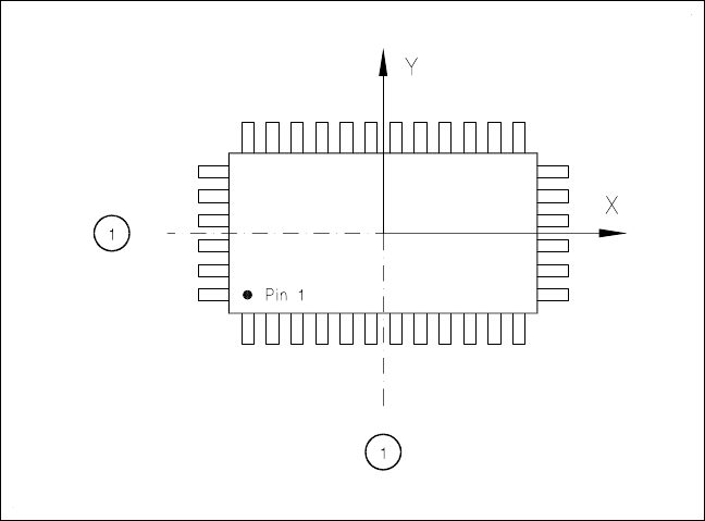
5.3.4 Criteria for Recognition of Components
Shape of the Components
With optical components centering not only regular but also irregular components can be centered. The maxi-
mum number of leads horizontally and vertically is 99 in each case.
Criteria for regular components
Definition
A component is deemed to be regular when it satisfies the following four conditions:
– rectangular package shapes (special case: square shape)
– only one lead type per side
– only one lead group per side
– opposite lead groups will be located symmetrically with respect to the two main axes
(x and y axes).
Fig. 5.3.1 Regular component
- Key to Fig. 5.3.1
1 Axis of symmetry
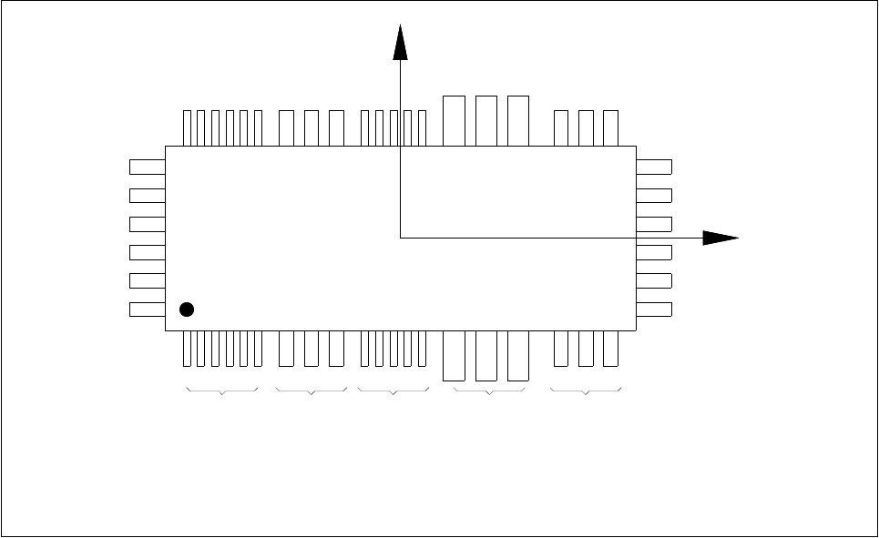
Criteria for irregular components
Definition
A component is deemed to be irregular when it does not satisfy the conditions for regular components.
Additional conditions for centering with the component vision system:
– In any one row up to 3 different lead types are permitted.
– In any one row up to 15 groups are permitted.
5 Vision Functions SIPLACE 80S-20/F4/F5 User Manual
5.3 Component Vision System 05/99 Issue from Software Version SR.405.xx
5 - 30 Line engineer
Fig. 5.3.2 Example of irregular components
Pitch deviation
For each component the pitch deviation (which is the distance from the center of one lead to the center of the
next) can be edited separately in the GF editor. If this value is exceeded, the component will not be centered
and therefore not inserted.
Limit value for quality measurement
The components must not exceed the limit values for quality measurement as then they would not be
inserted:
– Difference in the number of leads between the original and the model.
– Pitch deviation larger than the value in the GF file.
– Larger orthogonality error than specified in the GF file.
– Larger deviations of the external dimensions.
– Deviation of the central point greater than the permitted positional tolerance for pick-up.
X
Pin 1
Y
X
Pin 1
Type 1 Type 2 Type 1 Type 3 Type 2
Group 1 Group 1 Group 2 Group 1 Group 2