80S-2080F480F5.pdf - 第348页
5 Vision Functions SIP LACE 80S-20/F4/F5 Us er Manual 5.6 Test Component 05/99 Issue from Software V ersion SR.405.xx 5 - 116 Line en gineer 5.6.4.14 Information on Measurement Methods As far as convent ional co mponen t…
SIPLACE 80S-20/F4/F5 User Manual 5 Vision Functions
05/99 Issue from Software Version SR.405.xx 5.6 Test Component
Line engineer 5 - 115
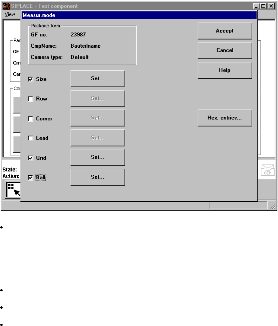
Measuring mode
menu
Click on the ’Measuring
mode’ field to call up the
Measuring mode
menu.
Fig. 5.6.34
Test component
menu,
Measur. mode
option
In the left column of the box, the desired measuring method can be activated or deactivated by clicking
with the mouse. A cross indicates that you have activated the measuring method. The ‘Setting' field for
calling up the sub-menu changes from grey to black.
Please note that
– there is currently no option for setting the ’Ball’ measuring mode.
– You can only use measuring modes that have been activated.
Use the ‘Hex input’ field to call up the ‘Measuring mode 2’ input menu for directly entering hex values.
Please follow the instructions on page 5 - 114.
Select ‘Accept’ to close the ‘Measuring mode’ menu. The modified measuring conditions will be entered
into the package form file on the station computer.
Select ‘Abort’ to interrupt the operation without transferring the data and to return to the ‘Test component’
menu.

5 Vision Functions SIPLACE 80S-20/F4/F5 User Manual
5.6 Test Component 05/99 Issue from Software Version SR.405.xx
5 - 116 Line engineer
5.6.4.14 Information on Measurement Methods
As far as conventional components with lead connections are concerned, component centering is essentially
based on four measurement methods used to determine the position (x and y coordinates, Φ = skew) of the
component and the lead parameters:
– Size-driven mode
– Row-driven mode
– Corner-driven mode
– Lead-driven mode
For BGAs (B
all Grid Arrays) and flip-chips new algorithms have been implemented in order to determine the
position (x and y coordinates, Φ = skew) of the component and the ball parameters (see ’Measure Compo-
nent Option’ on Page 5 - 92.):
– Grid-driven mode
– Ball-driven mode
In accordance with your specifications any measurement method can be omitted from this sequence. How-
ever, it is not possible to change the way this sequence runs.
Definition of the measuring methods
Size-driven
This measurement method has been especially developed for small components. On the basis of the infor-
mation on dimension parameters the position and rotation of small components is determined rapidly and
reliably.
This method is very resistant to unwanted intrusive elements such as ink markings.
The size-driven mode also employs profiling. You can have the profile formed along either the width
or
the
length of the component. You should make your choice within the options field. The default selection is for
profiling along the longer side.
Row-driven
This measurement method is based on information from one row of leads.
This method is very fast and supplies approximate values for the coordinates and rotational angle of the
component.
Corner-driven
(Component inspection)
The measurement results provide precise information on the coordinates and rotation of the component,
the number of leads, the pitch and the row offset.
This method is not sensitive to fluctuations in the lead dimensions.
Lead-driven (Leads inspection)
This method is used to obtain information from an inspection of every single lead.
The following combinations of measurement methods are used:
– Size-driven — corner-driven — lead-driven (see the table in Section 5.6.4.15) or
– Row-driven — corner-driven — lead-driven (see the table in Section 5.6.4.15)
SIPLACE 80S-20/F4/F5 User Manual 5 Vision Functions
05/99 Issue from Software Version SR.405.xx 5.6 Test Component
Line engineer 5 - 117
Grid-driven
(component inspection with the 80F
4
or 80F
5
machines)
The measurement results will provide information on the approximate coordinates and approximate rota-
tion of the component. In addition, you will be informed of the quality of measurement.
Ball-driven
(determining the balls position with the 80F
4
or 80F
5
machines)
The measurement results will provide precise information on the approximate coordinates and approxi-
mate rotation of the component. In addition, you will be informed of the maximum ball offset and the quality
of measurement.
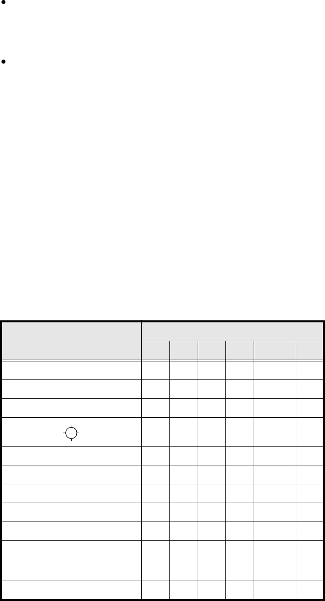
5.6.4.15 Recommendations regarding the Optimum Sequence of Measurement
Methods
The following table contains our recommendations for the optimum sequence of measurement methods for
particular components. The following abbreviations are used:
B = ball-driven
C = corner-driven
G = grid-driven
L = lead-driven
R = row-driven
S = size-driven
*)
L applies to irregularly shaped components with separate windows
Component Measurement sequence
S R G C L B
MELF S L
CHIP S L
SOT S C L
SL
SOJC6 S C
SOJC14 R C
LCC R C L
PLCC R C L
QFP R C L
TAB R C
L
*)
BGA, Flip-Chip S G B
Bare Dies S
Tab. 5.6.1 Optimum sequences of measurement methods