80S-2080F480F5.pdf - 第134页
2 Introduction and Ba sic Concepts SIPLACE 80S-20/F4/F5 User Manual 2.4 Brief Description and Principles of the User Interface 05/99 I ssue from Software Version SR.405.xx 2 - 50 2.4.4.1 1 Displa y PCB Ba rcode (Option) …
SIPLACE 80S-20/F4/F5 User Manual 2 Introduction and Basic Concepts
05/99 Issue from Software Version SR.405.xx 2.4 Brief Description and Principles of the User Interface
2 - 49
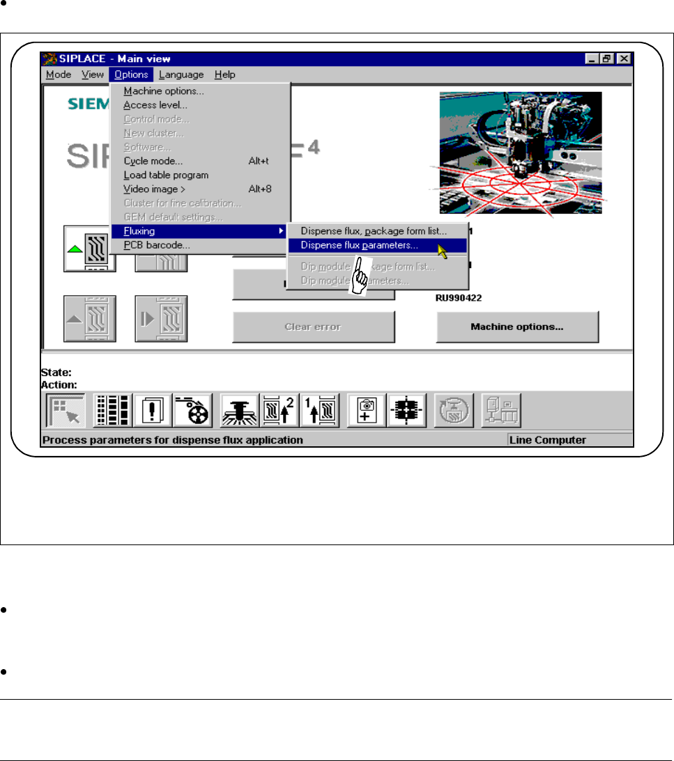
2.4.4.10 Flux Application (Option)
In order to apply flux for placing flip-chips on a PCB, the process data for the flip-chip must be entered in a list
and general flux application parameters must be entered on the station computer.
Select the
Fluxing
submenu from the
Options
menu on the menu bar
.
Fig. 2.4.13 Flux application option
l Dispense flux, package form list ...
Use this menu to add and edit flip-chip components with an associated package form (GF) no.
l Dispense flux parameters ...
Select the "Dispense flux parameters ..." menu in order to specify data for the flux application sequence.
PLEASE NOTE
The complete range of functions is described in Chapter 11 of this User Manual.
2 Introduction and Basic Concepts SIPLACE 80S-20/F4/F5 User Manual
2.4 Brief Description and Principles of the User Interface 05/99 Issue from Software Version SR.405.xx
2 - 50
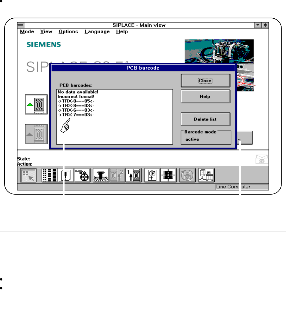
2.4.4.11 Display PCB Barcode (Option)
This menu is used to display the last barcode to be read by the PCB barcode reader in a list box.
It also indicates whether the barcode was read incorrectly or a start signal or the wrong signal occurred, or
whether no data was available.
Select the
PCB barcode
submenu from the
Options
menu on the menu bar.
Fig. 2.4.14 Display PCB barcode
- Key to Fig. 2.4.14
1 List box 2 Status display
Click on the Delete list button to delete the list.
The status display in the menu window shows the operating status for barcode mode. This operating sta-
tus is activated and deactivated by the line computer.
PLEASE NOTE
This menu is only active if the PCB bar code option has been installed and activated in the machine options.
1 2
SIPLACE 80S-20/F4/F5 User Manual 2 Introduction and Basic Concepts
05/99 Issue from Software Version SR.405.xx 2.4 Brief Description and Principles of the User Interface
2 - 51
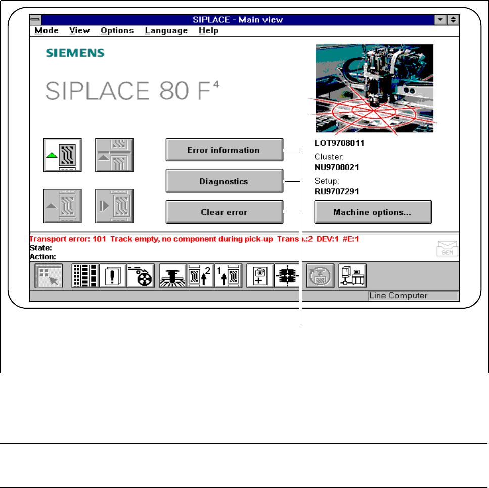
2.4.5 Troubleshooting and Diagnostics Buttons
Fig. 2.4.15 Troubleshooting and diagnostics
- Key to Fig. 2.4.15
1 Troubleshooting and diagnostic buttons
PLEASE NOTE
The complete range of functions is described in Chapter 7 of this User Manual.
2.4.5.1 Error Info
If errors occur while the PCB is being processed, you can call up information on the error. This information can
be called from the main view or by using “Display error“.
1