80S-2080F480F5.pdf - 第71页
SIPLACE 80S-20/F4/F5 User M anual 1 Operational Safety 05/99 Issue from Software Version SR.405.xx 1.4 Disabling the compressed air supply and discharging the pressure 1 - 33 1.4 Disabling the compr essed air supply and …
1 Operational Safety SIPLACE 80S-20/F4/F5 User Manual
1.3 Residual voltages in the servo unit and discharge times when placement system is switched off 05/99 Issue from Software Version
SR.405.xx
1 - 32
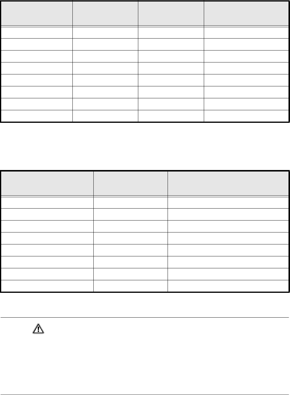
1.3.1 Operating voltages, residual voltages and discharge times after
pressing the emergency stop button
1.3.2 Residual voltages and discharge times after switching off at the
main switch
CAUTION
To avoid losing data, evaluate the following criteria before switching off your automatic placement system (apart
from in emergencies):
– Has the placement system finished transmitting machine, set-up and working data?
– Has the placement system finished processing the PCB?
– Has the placement system completed the run-up phase?
– Has the Windows NT operating system been shut down correctly?
Test socket 00X
measured at 007
(GND)
Voltage
in normal mode
Residual voltage
after emergency stop
Discharge times
of electrolytic
capacitors at 12 VDC
001 70 VDC 10 VDC < 2 sec
002 30 VDC 30 VDC –
003 30 VDC < 12 VDC < 2 sec
004 24 VDC 24 VDC –
005 12 VDC 12 VDC –
006 5 VDC 5 VDC –
008 70 VDC 10 VDC < 2 sec
009 100 VDC 10 VDC < 1 sec
Tab. 1.3 - 1 Operating voltages, residual voltages and discharge times after pressing the emergency stop button
Test socket 00X
measured at 007 (GND)
Residual voltage
when main switch is off
Discharge times
of electrolytic
capacitors at 12 VDC
001 < 12 VDC < 2 sec
002 < 12 VDC < 2 sec
003 < 12 VDC < 2 sec
004 0 VDC –
005 0 VDC –
006 0 VDC –
008 < 12 VDC < 2 sec
009 < 12 VDC < 1 sec
Tab. 1.3 - 2 Residual voltages and discharge times after switching off at the main switch
SIPLACE 80S-20/F4/F5 User Manual 1 Operational Safety
05/99 Issue from Software Version SR.405.xx 1.4 Disabling the compressed air supply and discharging the pressure
1 - 33
1.4 Disabling the compressed air supply and dis-
charging the pressure
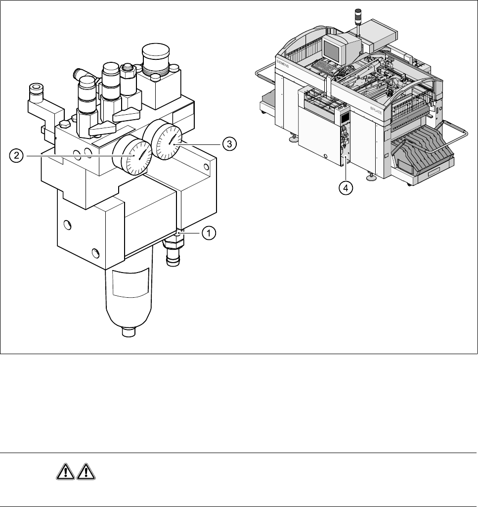
The compressed air working pressure is set to 5,1 bar, although it may fluctuate between 5.0 and 5.3 bar.
The position of the compressed air unit is indicated by item 4 in Fig. 1.4.1. The compressed air supply to the
automatic placement system can be interrupted using the shut-off valve (item 1 in Fig. 1.4.1).
- You must remove the cover plate to use the shut-off valve.
- Turn the lever on the shut-off valve (item 1 in Fig. 1.4.1) from the vertical to the horizontal position.
- Watch the working pressure gauge and the pressure gauge for the compressed air supply to the stopper
(item 2 and 3 in Fig. 1.4.1)
When the automatic placement system is switched on, the pressure discharges to 0 bar within 1 minute.
Fig. 1.4.1 Compressed air unit on the automatic placement system
- Key to Fig. 1.4.1
1 Shut-off valve lever in the ’CLOSED’ position2 Working pressure gauge
3 Pressure gauge for the stopper working pressure4 Position of the compressed air unit on the
placement system
WARNING
NEVER disconnect compressed air lines while they are pressurized. Risk of injury!
1 Operational Safety SIPLACE 80S-20/F4/F5 User Manual
1.4 Disabling the compressed air supply and discharging the pressure 05/99 Issue from Software Version SR.405.xx
1 - 34