80S-2080F480F5.pdf - 第397页
SIPLACE 80S-20/F4/F5 User M anual 5 Vision Func tions 05/99 Issue from Software Version SR .405.xx 5.10 Test Component: Supp lements to the 80F4 or 80F5 Machines Line en gineer 5 - 165 With th e mouse p ointer ma rk a co…
5 Vision Functions SIPLACE 80S-20/F4/F5 User Manual
5.10 Test Component: Supplements to the 80F4 or 80F5 Machines 05/99 Issue from Software Version SR.405.xx
5 - 164 Line engineer
5.10.1
Select Package Form
Menu
Following selection of the
Test component
menu the
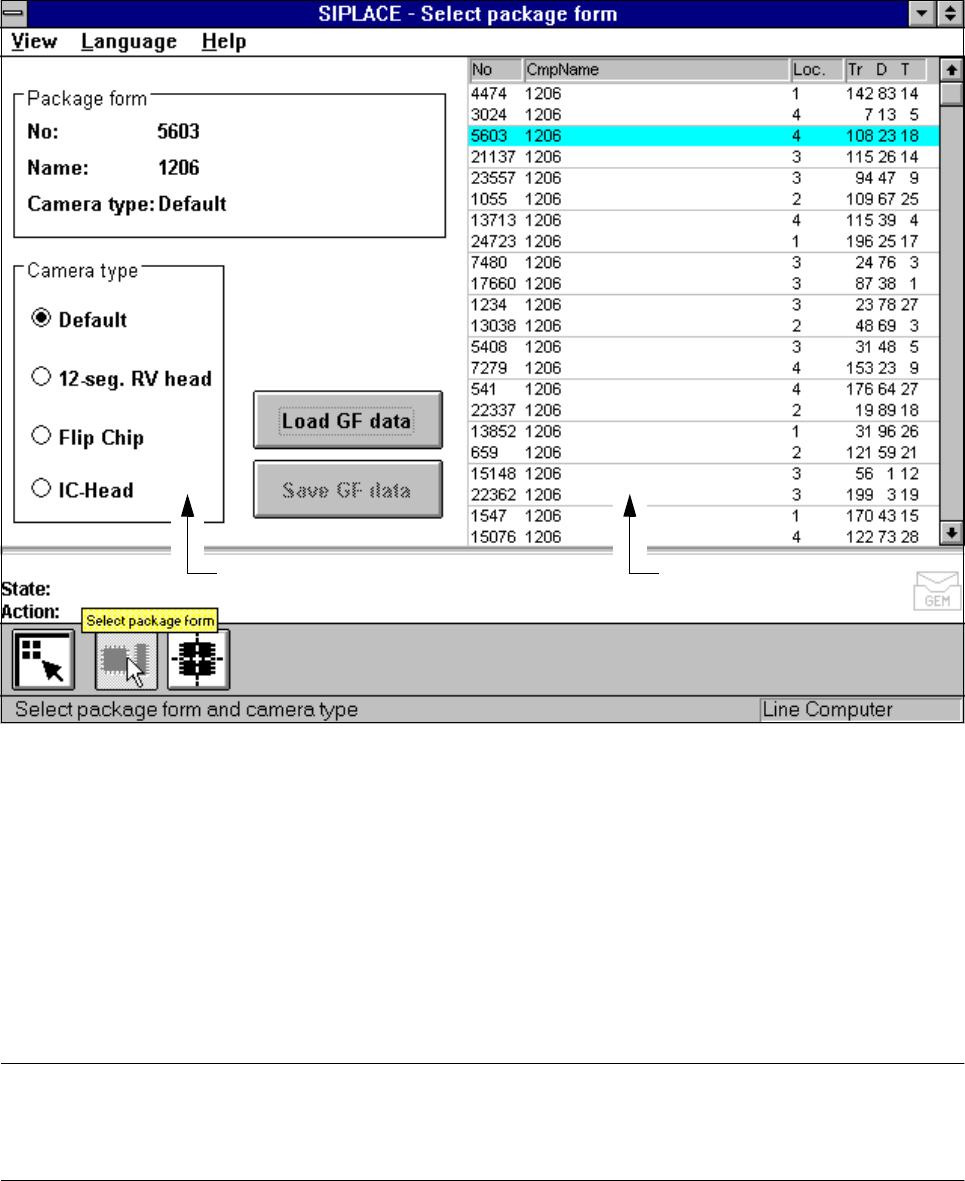
Select package form
menu will drop down. Here you
can specify a package form and the corresponding camera type.
Fig. 5.10.2
Select package form
menu
If you had previously changed measurement conditions or package form you will be asked where you wish to
discard or save the data. For a description of this please refer to Section 5.6.3 from Page 5 - 81.
The menu that appears after this query differs from that of the 80S-20 only in that the 80S-20 automatic place-
ment system has a component vision system on both revolver placement heads, while the 80F
4
/F
5
-automatic
placement system has a component vision system on the 12x or 6x revolver head, and one or two component
vision systems can be used on the machine frame for the IC placement head. The component vision system
with IC camera centers fine-pitch components and BGAs, while the component vision system with FC camera
centers flip-chips and fine-pitch components.
PLEASE NOTE
Only select the revolver head, IC head or IC head/flip-chip camera type if you want to insert components of
the same type with both the 12x or 6x revolver head and the IC head.
Camera type
options field
Lists field
SIPLACE 80S-20/F4/F5 User Manual 5 Vision Functions
05/99 Issue from Software Version SR.405.xx 5.10 Test Component: Supplements to the 80F4 or 80F5 Machines
Line engineer 5 - 165
With the mouse pointer mark a component from the list field or the vision system in the
Camera type
options field.
Click on the
Load GF data
button. The data are transferred to the program.
Click on the
Main view
symbol, break off the dialog without saving and return to the
Main view
menu.
5.10.2
Test Component
Menu
5.10.2.1
Select Component Type
Option
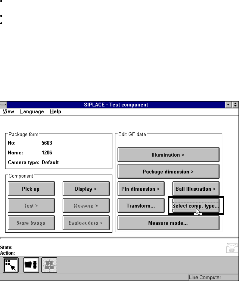
With the 80F
4
or 80F
5
machines, the
Test component
menu (for a description see Section 5.10.2, Page 5 -
165) also includes the
Select component type
option.
Fig. 5.10.3
Test component
menu (80F
4
or 80F
5
)
When you select this option the following menu will open.
5 Vision Functions SIPLACE 80S-20/F4/F5 User Manual
5.10 Test Component: Supplements to the 80F4 or 80F5 Machines 05/99 Issue from Software Version SR.405.xx
5 - 166 Line engineer
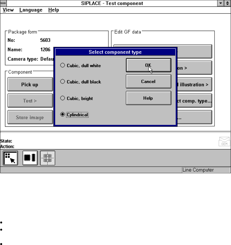
Fig. 5.10.4
Test component
menu,
Select component type
option
You should select this option when centering errors occur with standard lighting. The 4 possibilities available
here for selection enable you to match the lighting optimally to the component in question. Each of these
options contains certain combinations of the flat, middle and steep types of illumination.
Mouse functions
Use the mouse pointer to mark the corresponding component type.
With
OK
confirm your input and the option field will be closed. You will be returned to the
Test component
menu.
Click on
Cancel
to quit the option field without taking over any modifications you may have changed.