80S-2080F480F5.pdf - 第535页
SIPLACE 80S-20/F4/F5 User M anual 9 Maintenance 05/99 Issue from Software Version SR.405.xx 9.6 IC Head (SIPLACE 80F4/F5) 9 - 69 Sp are Part s Silencer, G-1/8 CV05 HS , from ite m no. 00308 498-01. Move th e IC hea d to …
9 Maintenance SIPLACE 80S-20/F4/F5 User Manual
9.6 IC Head (SIPLACE 80F4/F5) 05/99 Issue from Software Version SR.405.xx
9 - 68
9.6.4.1 Replacing the Silencer
NOTE
Contamination of the filter in the silencer may lead to faults in the vacuum generation unit.
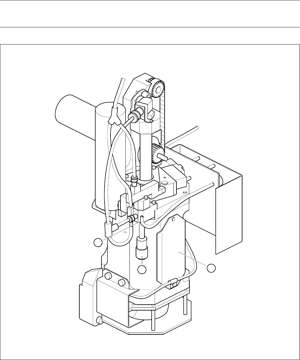
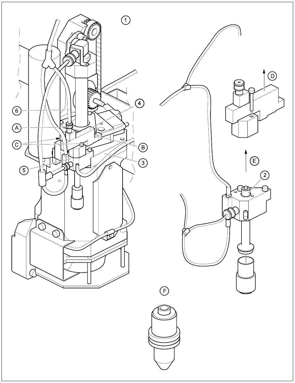
Fig. 9.6.5 Replacing the silencer filter of the vacuum generator
- Key to Fig. 9.6.5
1 IC head
2Silencer cap
3 Vacuum generator
2
3
1

SIPLACE 80S-20/F4/F5 User Manual 9 Maintenance
05/99 Issue from Software Version SR.405.xx 9.6 IC Head (SIPLACE 80F4/F5)
9 - 69
Spare Parts
Silencer, G-1/8 CV05 HS, from item no. 00308498-01.
Move the IC head to the service position.
Switch the machine off at the main switch.
Remove the cover over the compressed air unit in the machine base. To do so, use a size 3 socket-head
screwdriver to remove the two hexagon socket screws.
In addition, turn off the compressed air supply at the shut-off cock in the compressed air unit (see Fig.
9.3.5).
Unscrew and remove the silencer. Place the new silencer in position and screw it down.
Unscrew and remove the silencer.
Place the new silencer in position and screw it down.
9.6.5 Cleaning the Vacuum Nozzle and O-Rings, Checking and Greas-
ing the O-Rings
NOTE
Contamination of the vacuum nozzle may lead to vacuum faults.
Check whether the compressed air specifications have been complied with, if necessary carry out mainte-
nance of the compressed air unit.
Spare parts:
1 o-ring, 5 x 1.5 NBR 70B, from item no. 00305480-01
1 o-ring, 8 x 1.0 NBR 70B, from item no. 00201179-01
9.6.5.1 Preparatory Work
The IC head is in the service position, the machine is switched off at the main switch, the compressed air is
also switched off at the stop valve of the compressed air unit.
Remove the vacuum nozzle. The sequence of work is shown in Fig. 9.6.6 and the following key.
9.6.5.2 Maintenance of the Vacuum Nozzle and O-Rings
Remove the o-rings and the sleeve from the vacuum nozzle and carry out maintenance as shown in Fig.
9.6.7.
Re-assemble the parts after maintenance and insert the vacuum nozzle vertically with a slight twist into the
vacuum generator as far as the stop. The o-ring in the annular groove in the nozzle must slide into the
hole.
9 Maintenance SIPLACE 80S-20/F4/F5 User Manual
9.6 IC Head (SIPLACE 80F4/F5) 05/99 Issue from Software Version SR.405.xx
9 - 70
Fig. 9.6.6 Removing the vacuum nozzle for maintenance