80S-2080F480F5.pdf - 第92页
2 Introduction and Ba sic Concepts SIPLACE 80S-20/F4/F5 User Manual 2.1 Display and Controls on the Machine 05/99 Issue from Software V ersion SR.405.xx 2 - 8 2.1.5 BA R CODE Reader (Option) The bar c ode read er will he…
SIPLACE 80S-20/F4/F5 User Manual 2 Introduction and Basic Concepts
05/99 Issue from Software Version SR.405.xx 2.1 Display and Controls on the Machine
2 - 7
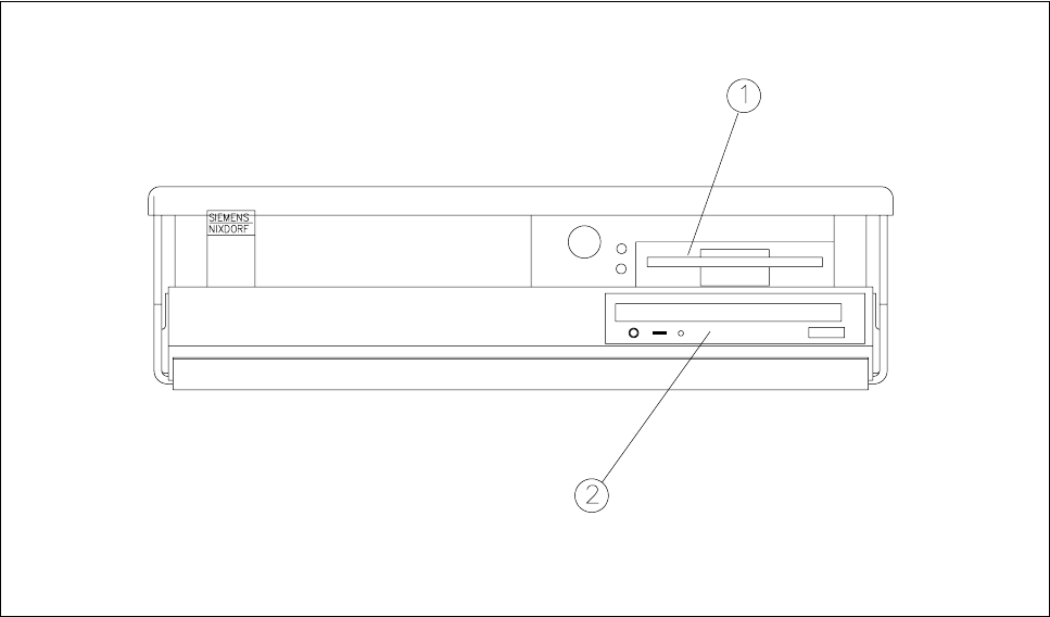
2.1.4 Station Computer
The station computer of the SIPLACE 80S-20/F
4
/F
5
is an IBM-compatible PC. A small desktop model is used
as the housing.
Fig. 2.1.3 Desktop computer
- Key to Fig. 2.1.3
1 3,5" floppy drive 2 CD-ROM drive
2 Introduction and Basic Concepts SIPLACE 80S-20/F4/F5 User Manual
2.1 Display and Controls on the Machine 05/99 Issue from Software Version SR.405.xx
2 - 8
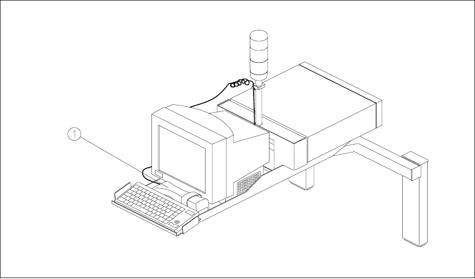
2.1.5 BAR CODE Reader (Option)
The bar code reader will help you, particularly under production conditions, to read quickly and reliably com-
ponent bar codes from component reels and track bar codes from the bar code strip on the machine. As each
data record is successfully read in, this is acknowledged by an acoustic signal.
Fig. 2.1.4 Bar code reader
- Key to Fig. 2.1.4
1 Bar code reader
SIPLACE 80S-20/F4/F5 User Manual 2 Introduction and Basic Concepts
05/99 Issue from Software Version SR.405.xx 2.1 Display and Controls on the Machine
2 - 9
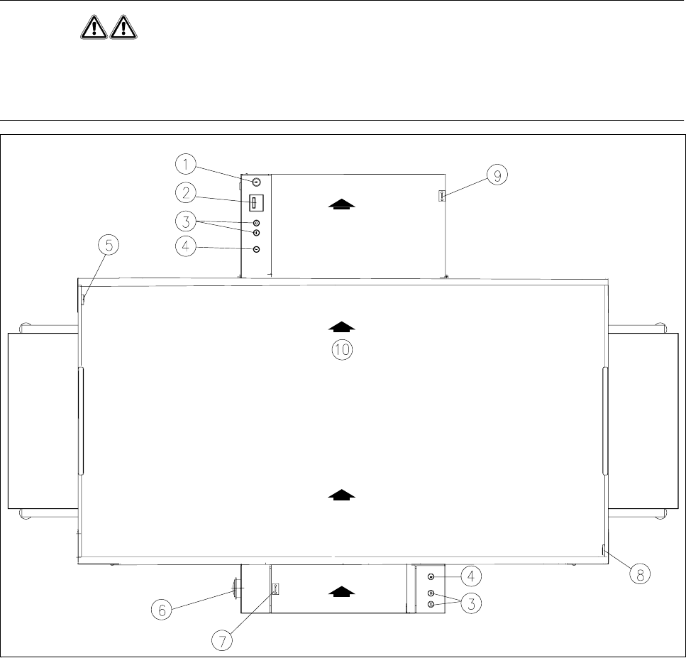
2.1.6 Switches on the Machine
Fig. 2.1.5 shows the position on the machine of the main switch, the cover switch, pushbuttons for start and
stop, the EMERGENCY STOP mushroom-head push-button, and the key-operated switch.
WARNING
Only appropriately qualified personnel are permitted to use the key-operated switch for servicing or mainte-
nance work. In all other cases the key must be kept secure against unauthorized access as otherwise the out-
come could be serious injury to the person or damage to the machine.
Fig. 2.1.5 Position of the switches on the machine
- Key to Fig. 2.1.5
1 Key-operated switch 2 Components counter
3 Start and stop buttons 4 Emergency stop mushroom-head push-button
5 Left cover switch 6 Main switch
7 Cover switch on cover of input belt 8 Right cover switch
9 Cover switch on cover of output belt 10 Transport direction