80S-2080F480F5.pdf - 第651页
SIPLACE 80S-20/F4/F5 User M anual 11 Station Extensions/Options 05/99 Issue from Software Version SR.405.xx 11.7 Dispenser Flux Application Unit for SIPLACE 80F4/F5 11 - 35 1 1.7 Dispen ser Flux A pplication Un it for S …

11 Station Extensions/Options SIPLACE 80S-20/F4/F5 User Manual
11.6 Ceramic Substrate Centering 05/99 Issue from Software Version SR.405.xx
11 - 34
l Structure of the fiducial
Proposal 1
Structure of the
fiducial
Black resistor paste as background. Conductor paste printed onto this as fiducial.
Recommendation Background 0.75 mm larger than the fiducial on all sides.
Type of lighting Normal light
Advantage Good contrast; good definition
Reference Conductor layer
Assessment This combination gives the best results. Highly recommended.
Proposal 2
Structure of the
fiducial
Fiducial made of conductor track material; for example, 6119 and with passivation
glass 4330 overprinted.
Type of lighting Oblique light
Advantage No additional operational step necessary
Reference Conductor layer
Assessment Fiducials are not so well defined as with Proposal 1. Recommended.
Proposal 3
Structure of the
fiducial
Fiducials made of the conductor track layer against a background of exposed ceramic
Type of lighting Oblique light or normal light (depending on the paste)
Advantage No additional operational step necessary
Reference Conductor layer
Comment Fiducials are not so well defined as with Proposal 2.
Fiducial imaging depends on the surrounding free area. Each circuit may need to be
taught separately.
Assessment Recommended with qualifications.
SIPLACE 80S-20/F4/F5 User Manual 11 Station Extensions/Options
05/99 Issue from Software Version SR.405.xx 11.7 Dispenser Flux Application Unit for SIPLACE 80F4/F5
11 - 35
11.7 Dispenser Flux Application Unit for SIPLACE 80F
4
/
F
5
11.7.1 General Comments
If flip-chip components are to be processed properly and reliably, a flux must be applied before the component
is inserted. This ensures that the soldering process which follows runs smoothly and dependably.
Once the flip-chip component has been picked up by the IC head and positional measurement carried out,
flux is applied to the placement position on the board. The quantity of flux which is to be applied can be spec-
ified for each package form.
Immediately following application of the flux the IC head inserts the flip chip. The IC head holds the flip-chip
component firmly in place on the board for a period of time which can be programmed and which is specific to
the package form. This causes the component to dry onto the flux and thus not be able to ‚float away‘.
Once all flip-chip components have been inserted, a programmable period of waiting follows, after which the
board conveyor is activated and the board transported onwards.
11 Station Extensions/Options SIPLACE 80S-20/F4/F5 User Manual
11.7 Dispenser Flux Application Unit for SIPLACE 80F4/F5 05/99 Issue from Software Version SR.405.xx
11 - 36
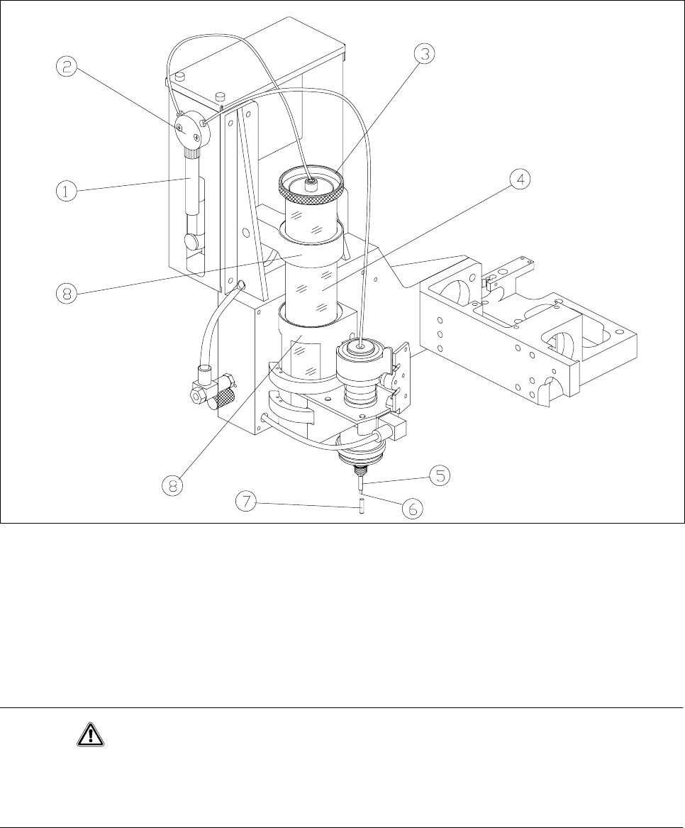
11.7.2 Function
The centrifuge tube is filled with flux and functions as a reservoir. The flux is sucked into the syringe via the
valve by means of a pump. The syringe now dispenses the preset amount of flux onto the placement position
via the valve and the tip of the dispensing needle.
Fig. 11.7.1 Flux application - overview
- Key to Fig. 11.7.1
1Syringe 2Valve
3 Reservoir lid 4 Reservoir (centrifuge tube)
5 Centering nozzle 6 Tip of the dispensing needle
7 Cover cap 8 Holder
CAUTION
If you expect the flux application unit to remain out of use for some time (more than approximately 1 hour), the
cover cap must be pulled over the centering nozzle. This prevents the flux crystallizing and clogging the cen-
tering nozzle.