80S-2080F480F5.pdf - 第252页
5 Vision Functions SIP LACE 80S-20/F4/F5 Us er Manual 5.2 PCB Vision System 05/99 Issue f rom Software Version SR.405.xx 5 - 20 Line en gineer Properti es of the s imple cr oss – The info rmationa l content i s somew hat…

SIPLACE 80S-20/F4/F5 User Manual 5 Vision Functions
05/99 Issue from Software Version SR.405.xx 5.2 PCB Vision System
Line engineer 5 - 19
5.2.5 Criteria for Creating Fiducials
Basically the same criteria apply to both fiducials and reject fiducials (ink dots): uniqueness of fiducial shapes
and readily detectable structures which stand out from their surroundings.
l Use existing structures as fiducials
Instead of fiducials you can also use uniquely identifiable structures within the layout. It should, however,
be remembered that the solder stop lacquer is frequently accompanied by a loss in contrast.
l Location of the fiducials
Position the fiducial where there are as few structures as possible and where the fiducial will stand out well
from its surroundings. Measuring outwards from the center of the fiducial, there should be a clearance on
each side at least equal to the fiducial size plus 1 mm.
l Type of fiducials
There are 2 types of fiducials:
– Positive fiducials
The fiducial extends beyond of the base material of the board.
– Negative fiducials
The fiducial is etched into the base material of the board.
l Fiducial shape
Always choose a well-structured, distinct shape as fiducial shape:
Recommended fiducial shapes:
Rectangle, square or circle
Properties
– Low informational content (fiducials can easily be confused with test dots).
NOTE
Make sure that there are no similar structures in the fiducial search area.
– Low space requirements in the layout
– Very robust with respect to different tinning procedures (e.g. hot-tinning).
Recommended fiducial dimensions
– for square and rectangles: Side length 1.2 mm - 2.2 mm
– for the circle: Diameter 1.2 mm - 2.2 mm
Double cross and single cross
Properties of the double cross
– Higher informational content
– More space required in the layout
– Sensitivity with respect to high tin-coatings (bare copper is preferable)
– If a fiducial quality is permitted which is too low you will run the risk of four incorrect positions being
recognized.
5 Vision Functions SIPLACE 80S-20/F4/F5 User Manual
5.2 PCB Vision System 05/99 Issue from Software Version SR.405.xx
5 - 20 Line engineer
Properties of the simple cross
– The informational content is somewhat lower than with the double cross
– Less space required in the layout than with the double cross.
– Less sensitive to high tin-coatings than with the double cross.
Dimensions of the fiducials:
Simple and double crosses
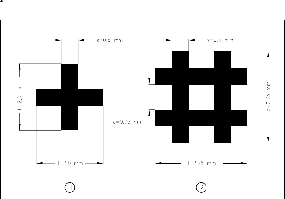
Fig. 5.2.3 Simple and double crosses with ideal dimensions
- Key to Fig. 5.2.3
1 Simple cross 2 Double cross
The minimum dimensions for a fiducial in length (l) and width (b) depend on the line thickness (s) and on the
structure of the fiducial.
– Length (l) and width (b)
For the good recognizability of a fiducial, the length and the width should be at least 0.9 mm with the sim-
ple cross and 1.8 mm with the double cross. The ideal dimensions for the simple cross are 2.0 mm and for
the double cross 2.75 mm. Under normal circumstances length and width will be equal.
– Line thickness (s)
The line thickness may vary according to standard structure widths and in addition will also depend on the
type of fiducial. However, you should ensure that the line is at least 0.3 mm thick. The ideal line thickness
for both fiducial types is 0.5 mm.
– Line spacing (a)
Line spacing also depends on the type of fiducial. Under no circumstances should line spacing fall below
0.5 mm. With the double cross the ideal spacing will be 0.75 mm.

SIPLACE 80S-20/F4/F5 User Manual 5 Vision Functions
05/99 Issue from Software Version SR.405.xx 5.2 PCB Vision System
Line engineer 5 - 21
– Thickness (d)
You should ensure, particularly with tin fiducials, that a warpage of more than 1/10 of the structure width is
not exceeded. If this degree of warpage is exceeded then under certain circumstances the fiducial may not
be evenly illuminated. This would lead to variations in reflection characteristics and unwanted reflections.
Recognition of the fiducials will then no longer be assured.
Recommended fiducial dimensions
Evaluation of the fiducial shapes
With tinned structures and higher dimensional stability (a low degree of etching variation) full circles or full
squares may be regarded as very satisfactory fiducial shapes (the ratio of fiducial thickness to presoldering
thickness will be large!). If dimensional stability falls, the full circle should be preferred to the square.
As far as the fiducial shapes of simple and double cross are concerned, bright copper is advantageous as
long as oxidation has not advanced too far.
l Surface of the fiducials
Make sure that the surface of the fiducial is as level as possible and with little oxidation. Avoid wetting the
fiducial with solder-stop lacquer as this could result in lowering the contrast with the background or pro-
duce unwanted reflections. Similar effects occur with tinned fiducials as well.
l Contrast of the fiducials
To ensure that fiducial recognition is of a high quality select a high brightness contrast between the fiducial
and the base material; in other words, bright fiducials on a dark base material and vice versa. For example,
on a copper or tin background apply dark fiducials. In the case of ceramic substrates with a bright surface
and unsatisfactory reflective properties it is often helpful to precoat with a dark resistance material in order
to improve contrast characteristics.
l Number of fiducials
When using ceramic substrates and small boards it will usually be sufficient to apply two fiducials. How-
ever, with larger boards it is recommended that three fiducials be defined. The individual fiducials can vary
in structure. You can simplify the recognition procedure if you use the same structure for each fiducial.
Fiducial type
Simple cross Double cross
Range Ideal range Range Ideal range
Length (l) 0.9 mm (min) 2.0 mm 1.8 mm 2.75 mm
Width (b) 0.9 mm (min) 2.0 mm 1.8 mm 2.75 mm
Line thickness (s) 0.3 - 1.5 mm 0.5 mm 0.3 - 0.75 mm 0.5 mm
Line spacing (a) — — 0.5 mm (min) 0.75 mm
Thickness (d) < 1/10 of the structure width < 1/10 of the structure width
Tab. 5.2.2 Recommened fiducial dimensions