80S-2080F480F5.pdf - 第13页
SIPLACE 80S-20/F4/F5 User M anual 0 Introduction 05/99 Issue from Software Vers ion SR.405.xx 0.2 Technical Data 0 - 9 0.2 T echnical Data 0.2.1 Siplace 80S-2 0 0.2.1. 1 Gantry Axes 1 and 2 0.2.1.2 12-nozzle Revolver Hea…
0 Introduction SIPLACE 80S-20/F4/F5 User Manual
0.1 General 05/99 Issue from Software Version SR.405.xx
0 - 8
0.1.5 On the SIPLACE 80F
5
automatic placement systems
The SIPLACE 80F
5
automatic placement system is a modular, high performance placement system with a 6-
nozzle revolver head and an IC placement head on a gantry. The components on the revolver head are
inserted first, followed by the components on the IC head. The 6-nozzle revolver head can process the entire
range of components, from the 0603 chip through to the QFP 208, if type 7 or type 8 nozzles are used for this
purpose (see chapter 17). The new optional component vision system (DCA option) can be used to insert flip-
chip components and bare dies up to 13 x 13 mm in size, in addition to standard components.
The placement quality is ensured by the PCB position detection system and the components are centered
using the vision system. The placement system is also now equipped with a new, pneumatically-controlled
tape cutter.
A coplanarity laser module and a flip-chip vision module for the IC head can now be used as optional extras.
A wafflepack changer may be used to supply the components.

SIPLACE 80S-20/F4/F5 User Manual 0 Introduction
05/99 Issue from Software Version SR.405.xx 0.2 Technical Data
0 - 9
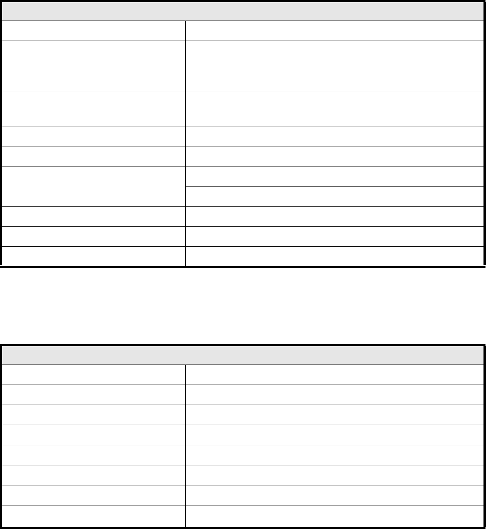
0.2 Technical Data
0.2.1 Siplace 80S-20
0.2.1.1 Gantry Axes 1 and 2
0.2.1.2 12-nozzle Revolver Head
Gantry axes 1 and 2
Drive D.C. servo motors
Path-measuring system Linear incremental scales
Resolution x / y axes 2.5 µm
Speed x axis 2.0 m/s
Speed y axis 2.0 m/s
12-nozzle revolver head
Programmable placement force (z axis) 2.0 N to 5.0 N
Nozzle types 21 (70x, 71x, 72x, 75x)
Segments 12
Components that can be assembled
Max. height 6.0 mm
Min. pitch 0.5 mm
Dimensions: 0.5 mm x 1.0 mm to 14 mm x 18 mm
Weight up to 2 grams
dp1/dp2 turning axes resolution
0.025
o
Star axis resolution
0.0025
o
Z axis stroke 16 mm
0 Introduction SIPLACE 80S-20/F4/F5 User Manual
0.2 Technical Data 05/99 Issue from Software Version SR.405.xx
0 - 10
0.2.1.3 Boards, Components, Tapes
0.2.1.4 Connection and Installation Data
Boards, components, tapes
Boards (PCB) transport system In-line transport with width adjustment
PCB format
50 mm x 50 mm to 460 mm x 460 mm with PCB buffer
50 mm x 50 mm to 508 mm x 460 mm without PCB buffer
(upon request)
Component-free guide edge of the
board
3 mm
Min. PCB thickness 0.5 mm
Max. PCB thickness 4.5 mm
Max. PCB warpage Upwards : 4.5 mm less PCB thickness
Downwards: 0.5 mm plus PCB thickness
PCB change time 2.5 sec.
Max. number of 8 mm tapes 80
Tape reel diameter Max. 15“ in the reel container
Connection and installation data
System voltage 230/400 V ± 10 % (50/60 Hz.)
System voltage (Option for USA) 110/208 V ± 10 % (50/60 Hz.)
Total connected load 5 kVA
Total power consumption 5 kW
Fuse protection 3 x 16 A
Compressed air supply Min. 5.5 bar / max. 10 bar
Entire compressed air consumption 400 NL/min.
Machine footprint
Permissible surface load > 1000kg/m
2