80S-2080F480F5.pdf - 第27页
SIPLACE 80S-20/F4/F5 User M anual 0 Introduction 05/99 Issue from Software Vers ion SR.405.xx 0.4 Overall View of Assemblies 0 - 23 0.4 Overall V iew of A ssemblies 0.4.1 Overall V iew of SIPLACE 80S-20 Fig. 0.4.1 Overal…

0 Introduction SIPLACE 80S-20/F4/F5 User Manual
0.3 Installation of the SIPLACE 80 Placement Machine 05/99 Issue from Software Version SR.405.xx
0 - 22
0.3.2 Supporting Surface
You must ensure that the machine is set up on a solid non-vibrating floor. If the floor is not level this can be
compensated for using the adjustable feet. The permissible surface load must be at least 1000 kg/m
2
.
0.3.3 Transportation
The machine is shipped from the factory without ancillaries such as keyboard, components tables and screen.
These parts must be fitted or connected before start-up.
A forklift truck or platform truck with a fork length of 2 m must be used for moving and installation.
The lifting points for the forklift truck are indicated in Fig. 0.3.1 by arrows.
0.3.4 Compressed Air Connection
Values are provided in the table in Section 0.2 ’Technical Data’
This is achieved by:
- oil-free compressors, e.g. Atlas Copco model ZR4
- compressed air washer-driers
- series X microfilters, e.g. from Zander
0.3.5 Installation
- The clearance between the individual stations must in each case amount to between 1 and 3 mm at the
PCB conveyors.
- To ensure that the PCBs are conveyed smoothly and without problems the stations should be positioned in
alignment with one another. This can be carried out with the aid of a taut cord or of a shim.
Adjust the feet such that the height of the PCB conveyor belts above floor amounts to 830 mm.
With the aid of a machine spirit level adjust the horizontal position of the station to an accuracy of
0.02 mm/m.
Lock the feet. After locking them, check the position of the machine and if necessary correct it. The feet of
the station must support the station evenly.
CAUTION
Remove all shipping braces from the machine.
Connect up the necessary electrical, mechanical and pneumatic connections in accordance with the Techni-
cal Data (see section 0.2 ’Technical Data’).
SIPLACE 80S-20/F4/F5 User Manual 0 Introduction
05/99 Issue from Software Version SR.405.xx 0.4 Overall View of Assemblies
0 - 23
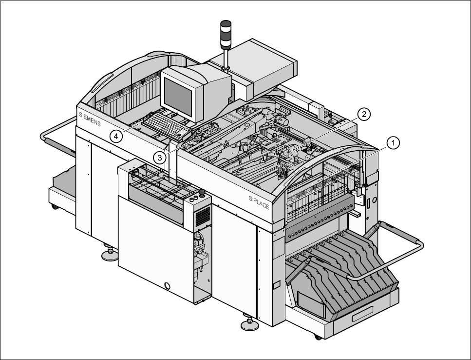
0.4 Overall View of Assemblies
0.4.1 Overall View of SIPLACE 80S-20
Fig. 0.4.1 Overall view of SIPLACE 80S-20
- Key to Fig. 0.4.1
1 Location 1 2 12-nozzle revolver head gantry 2
3 12-nozzle revolver head gantry 1 4 Location 3
0 Introduction SIPLACE 80S-20/F4/F5 User Manual
0.4 Overall View of Assemblies 05/99 Issue from Software Version SR.405.xx
0 - 24
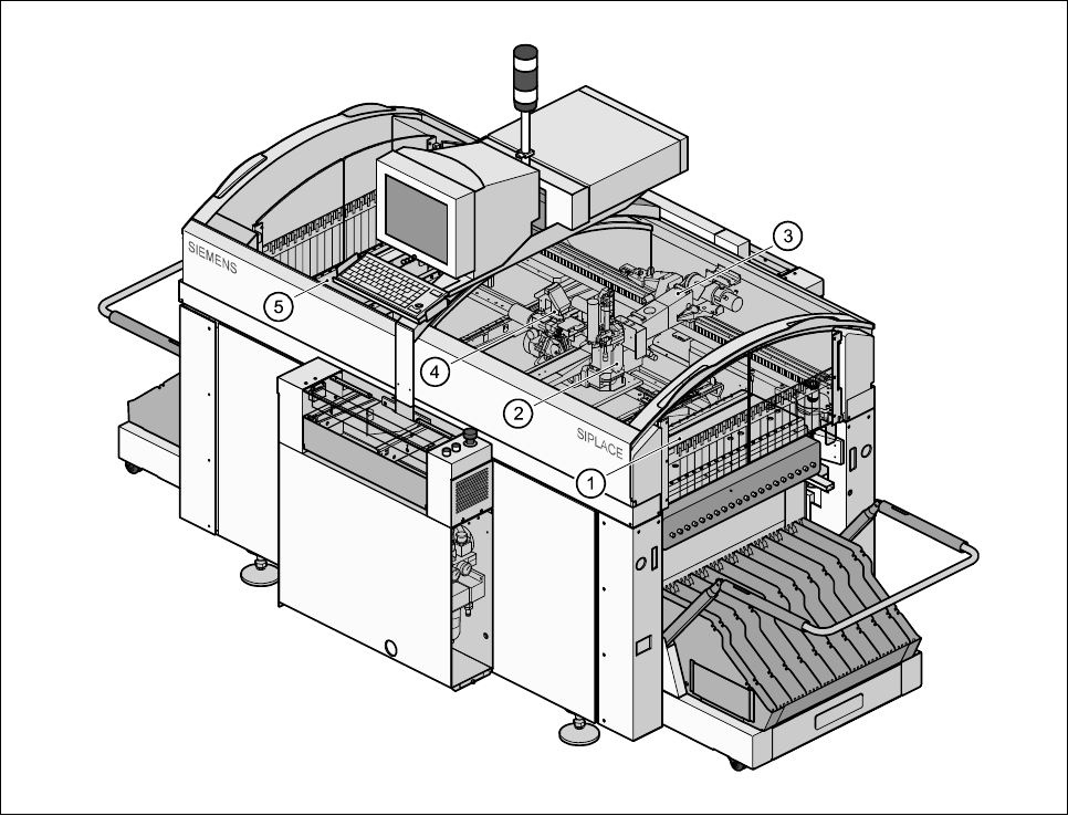
0.4.2 Overall View of SIPLACE 80F
4
Fig. 0.4.2 Overall view of SIPLACE 80F
4
- Key to Fig. 0.4.2
1 Location 1 2 IC placement head
3 Gantry 1 4 12-nozzle revolver head
5 Location 3