80S-2080F480F5.pdf - 第324页
5 Vision Functions SIP LACE 80S-20/F4/F5 Us er Manual 5.6 Test Component 05/99 Issue from Software V ersion SR.405.xx 5 - 92 Line en gineer 5.6.4 .4 Measure Component Opt ion NOTE This opti on can on ly be ac tivated i f…

SIPLACE 80S-20/F4/F5 User Manual 5 Vision Functions
05/99 Issue from Software Version SR.405.xx 5.6 Test Component
Line engineer 5 - 91
Fig. 5.6.19
Test component
menu,
Test component
video image
With the
Return
key you can call all defined individual steps in the measurement procedure one after the
other. Each time you press the
Return
key another measurement step is carried out and the results shown
on the screen.
Use
Esc
to quit the option. The video image closes and the
Test component
menu reappears.
GF No. = 5Test component
RET: Test component
5 Vision Functions SIPLACE 80S-20/F4/F5 User Manual
5.6 Test Component 05/99 Issue from Software Version SR.405.xx
5 - 92 Line engineer
5.6.4.4
Measure Component
Option
NOTE
This option can only be activated if you have already loaded a package form number and a component has
been picked up.
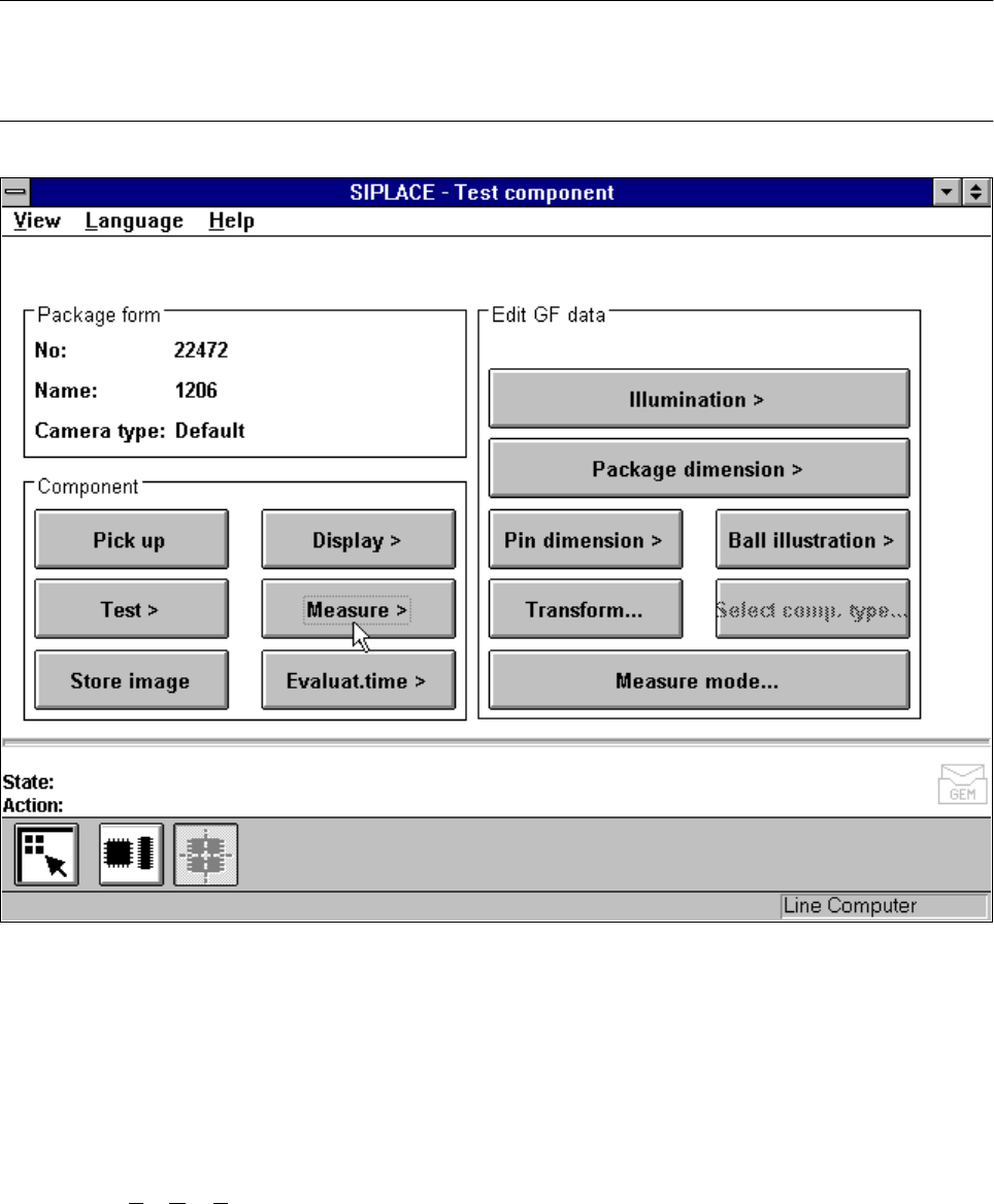
Fig. 5.6.20
Test component
menu,
Measure component
option
When this option is activated the following actions are started:
– The video image appears on the screen.
– The measurement command is given, using the predefined parameters.
– The MVS performs each component-specific measurement step in turn.
– The measurement values are displayed in the video image.
In addition, to conventional components with lead connections the 80F
4
or 80F
5
machines can also optically
center BGAs (B
all Grid Arrays) and flip-chips. The body of BGA and flip-chip components is made of passi-
vated silicon chips. Such bodies have strong reflective properties and their surfaces are wavy. The connec-
tions of these components take the form of balls with a diameter of at least 80 µm. Ball-grid arrays have their
connections, as the name suggests, arranged in the form of a grid - this means that they can be described in
terms of rows and columns.
SIPLACE 80S-20/F4/F5 User Manual 5 Vision Functions
05/99 Issue from Software Version SR.405.xx 5.6 Test Component
Line engineer 5 - 93
With flip-chips the balls are arranged irregularly over the body of the component body. The coordinates of
each connection will therefore need to be ascertained individually.
The IC head of the 80F
4
or 80F
5
machine picks up the BGAs or flip-chips from flatpack magazines. However
the evaluation procedures used to date for conventional components are no longer adequate for the optical
centering of BGAs or flip-chips. For this reason new evaluation methods and new lighting techniques have
been developed for the IC sensor and FC sensor in order that this new generation of components can be cen-
tered. BGAs and flip-chips which cannot be centered optically will be returned to the flatpack magazines by
the IC head.
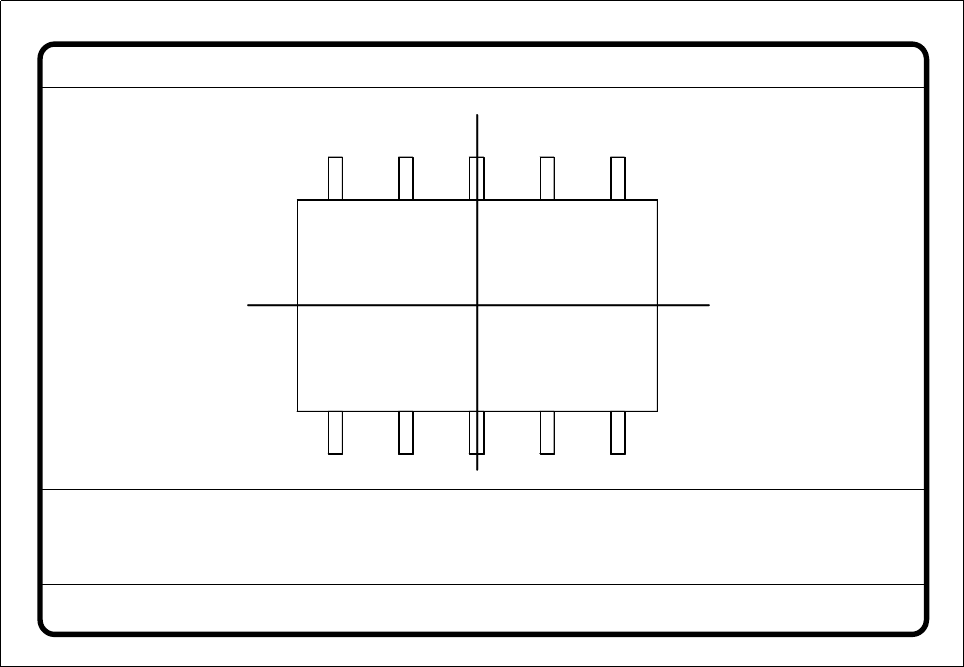
Fig. 5.6.21
Test component
menu,
Measure component
video image
Optical surveying of conventional components with lead connections with the 80S-20 and 80F
4
/F
5
placement machines:
The crosshairs indicate the component’s center. The component outlines are emphasized in color.
The measured values represent the geometric component parameters such as
– Lead skew
The value for lead skew will be indicated if you have selected the lead or ball measurement mode.
– Pitch
The value for pitch will be indicated if the corner measurement mode is active as the last measurement
step.
– Number of leads
– x / y offset
Measure component GF No. = 5
X offset = ... Y offset = ... Phi = ...
Orthogon = ...
No. of pins = ...
Quality fact. = ...
Length[mm] = ...
Width[mm] = ...
Spacing[mm] =
RET: Measure component
P.dev.[mm] =