80S-2080F480F5.pdf - 第384页
5 Vision Functions SIP LACE 80S-20/F4/F5 Us er Manual 5.7 Guidelines for Describi ng Package Forms 05/99 Issue from Software Version SR.405.xx 5 - 152 Line en gineer 5.7.9.3 Settings for Illuminating Components The stand…
SIPLACE 80S-20/F4/F5 User Manual 5 Vision Functions
05/99 Issue from Software Version SR.405.xx 5.7 Guidelines for Describing Package Forms
Line engineer 5 - 151
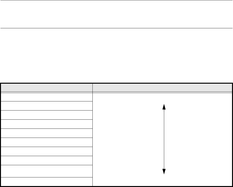
Middle illumination level
The middle illumination level can be used universally with a wide range of components. With bright compo-
nent bodies, ceramic components, µBGAs and flip-chips it should, however, only be used at lower intensity
levels.
Steep illumination level
The main application for the steep illumination level is for reflective leads, ceramic components and bright
component bodies. It is less suitable for bare dies, flip-chips or µBGAs.
NOTE
Most components will require a combination of these three illumination levels to achieve optimum illumination.
Using
one
illumination level will only be successful in exceptional cases.
5.7.9.2 Pseudo color representation
The pseudo color representation provides a powerful and objective assessment of the illumination, by repre-
senting a brightness value in a color.
A contrast of at least 4 color scales between the lead and body is required for a measurement. In the ‘Illumina-
tion’ menu of the package form manipulator, components are displayed in the pseudo color representation on
the station computer monitor.
Color scale Brightness
white light
yellow
orange
red
brown
green
light blue
blue
violet
black dark
Tab. 5.7.6 Conversion table for the pseudo color representation at the 6x revolver head
5 Vision Functions SIPLACE 80S-20/F4/F5 User Manual
5.7 Guidelines for Describing Package Forms 05/99 Issue from Software Version SR.405.xx
5 - 152 Line engineer
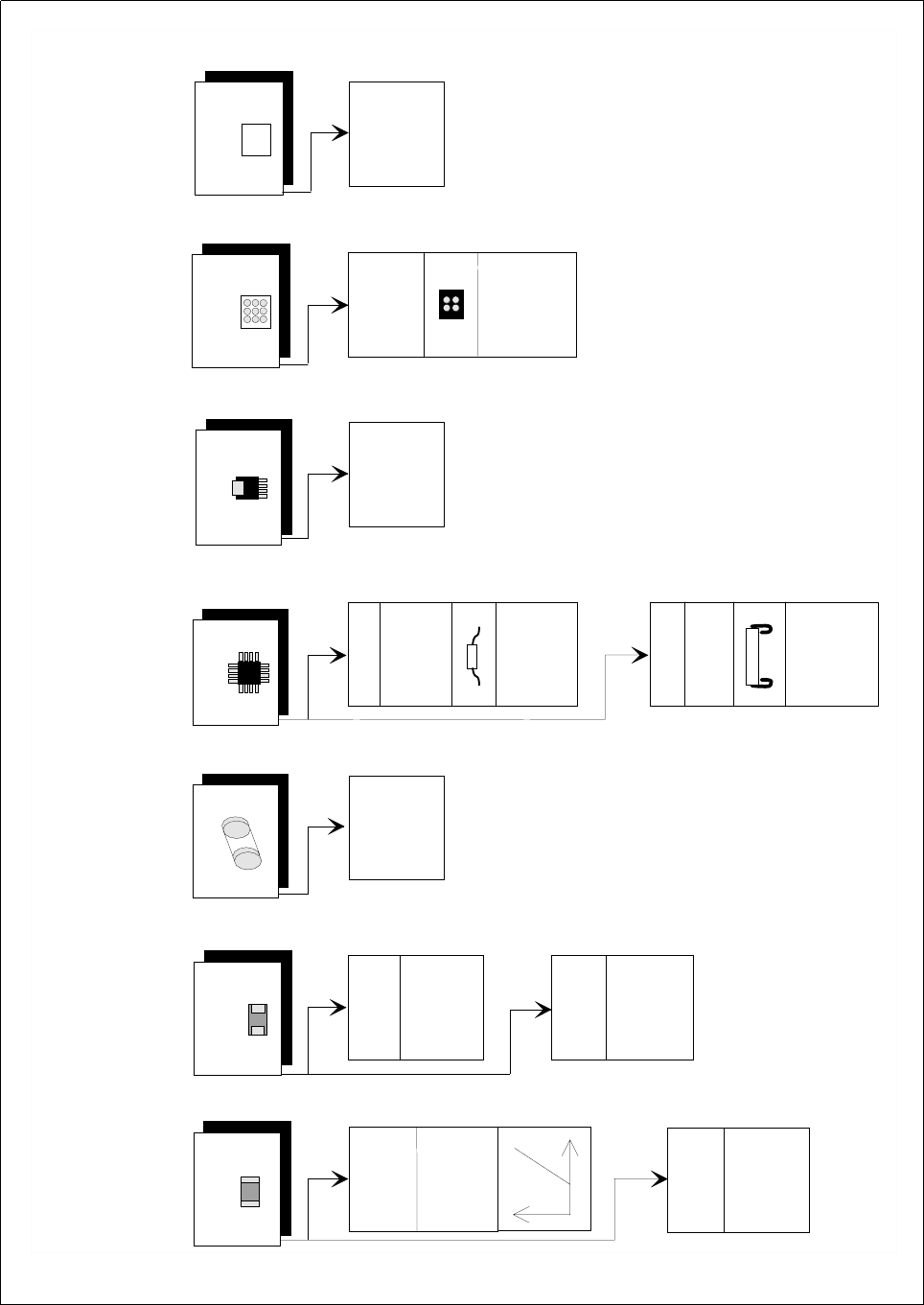
5.7.9.3 Settings for Illuminating Components
The standard range of components includes chips (0402 to 2220), tantalum capacitors, Melf components,
PLCCs, QFPs, SOs, SOJs, TSOPs, ICs, power components, flip-chips, µBGAs, BGAs and bare dies.
For the components which are listed below the GF interpreter in the station computer uses the default illumi-
nation parameters listed in Fig. 5.7.12:
– Chips (0402 to 2220)
– Tantalum capacitors (component bodies, non-reflective)
– Melf
– PLCC, QFP, SO, SOJ, TSOP, ICs, power ICs
– Flip-chips, µBGAs, BGAs
– Bare dies
As a rule you will not need to change the illumination parameters for the components.
SIPLACE 80S-20/F4/F5 User Manual 5 Vision Functions
05/99 Issue from Software Version SR.405.xx 5.7 Guidelines for Describing Package Forms
Line engineer 5 - 153
.
Fig. 5.7.12 Illumination Values for standard components at the 6x revolver head camera (DCA option) on the 80 F
5
placement
machine
A
d
justing the illum
ination o
f standard com
ponents
C
hip
IC
P
ow
er IC
M
elf
B
G
A
, µ
B
G
A
flip-chip
T
antalum
cap
acitor
B
G
A
,
µ
B
G
A
,
flip
-chip
0805 and
larger
020
1,
0402
,
0603
G
eneral
R
eflective
body
X
plane: 50
flat:
50
m
iddle: 50
steep:
50
G
ullw
ing
S
O
, S
O
T
,
T
S
O
P
Q
F
P
,
J-Lead
P
LC
C
255
1
50
X
plane
: 50
flat: 50
m
iddle: 50
steep: 50
X
plane
: 0
flat: 50
m
iddle:
80
steep
: 100
X
pla
ne
: 2
30
flat:
230
m
iddle: 20
steep: 20
X
plane
: 200
flat:
100
m
iddle:
40
steep: 40
X
plan
e
: 0
flat:
80
m
iddle: 50
steep: 50
X
p
lane
:
0
flat: 0
m
iddle: 100
steep:
20
X
pla
ne
: 15
0
flat: 30
m
iddle: 0
steep:
0
B
a
re D
ie
X
plane
: 0
flat:
80
m
iddle:
50
s
teep: 50
X
plane
: 0
flat:
0
m
iddle:
50
s
teep: 110