80S-2080F480F5.pdf - 第554页
9 Maintenance SIPLACE 80 S-20/F4/F5 User Manual 9.7 6x Revolver Head (8 000) 05/99 Issue from Software Version SR.405.xx 9 - 88 9.7.6 Cleaning V acuum/Forced Air V alves 9.7.6.1 Removing the V a lve Plunger Position the …
SIPLACE 80S-20/F4/F5 User Manual 9 Maintenance
05/99 Issue from Software Version SR.405.xx 9.7 6x Revolver Head (8000)
9 - 87
9.7.5 Greasing the Z Drive Unit
Materials and Equipment
A clean and lint-free cloth
Staburags N12 lubricating grease, from item no. 02100611-01
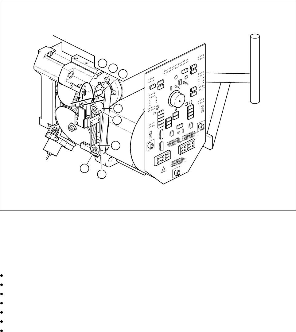
Fig. 9.7.7 Greasing the z drive unit
- Key to Fig. 9.7.7
1 Synchroflex toothed belt
2 Synchronizing pulley
3 Deflection wheels
Move the z axis to its top limit position.
Apply a little Staburags to a clean and lint-free cloth.
Grease the toothed belt sparingly in the area indicated in Fig. 9.7.7 (A).
Apply grease sparingly to the synchronizing pulley (B).
Apply grease sparingly to both deflection wheels.
Move the z axis back and forth repeatedly.
Wipe off excess grease with a cloth.
1
2
B
3
3
A
C
C
9 Maintenance SIPLACE 80S-20/F4/F5 User Manual
9.7 6x Revolver Head (8000) 05/99 Issue from Software Version SR.405.xx
9 - 88
9.7.6 Cleaning Vacuum/Forced Air Valves
9.7.6.1 Removing the Valve Plunger
Position the gantry concerned, with the revolver placement head over the PCB conveyor.
Switch off the placement system and disconnect the power supply.
Disconnect the compressed air supply.
Starting from the middle remove several feeders from the components changeover table.
Carefully push the gantry out to the stop by hand.
Depending on the valve adjustment drive responsible for prompting the error message you have to turn the
star by a certain angle to be able to remove and to clean the faulty valve:
Fault prompted by the ’pick-up/place’ valve adjustment drive
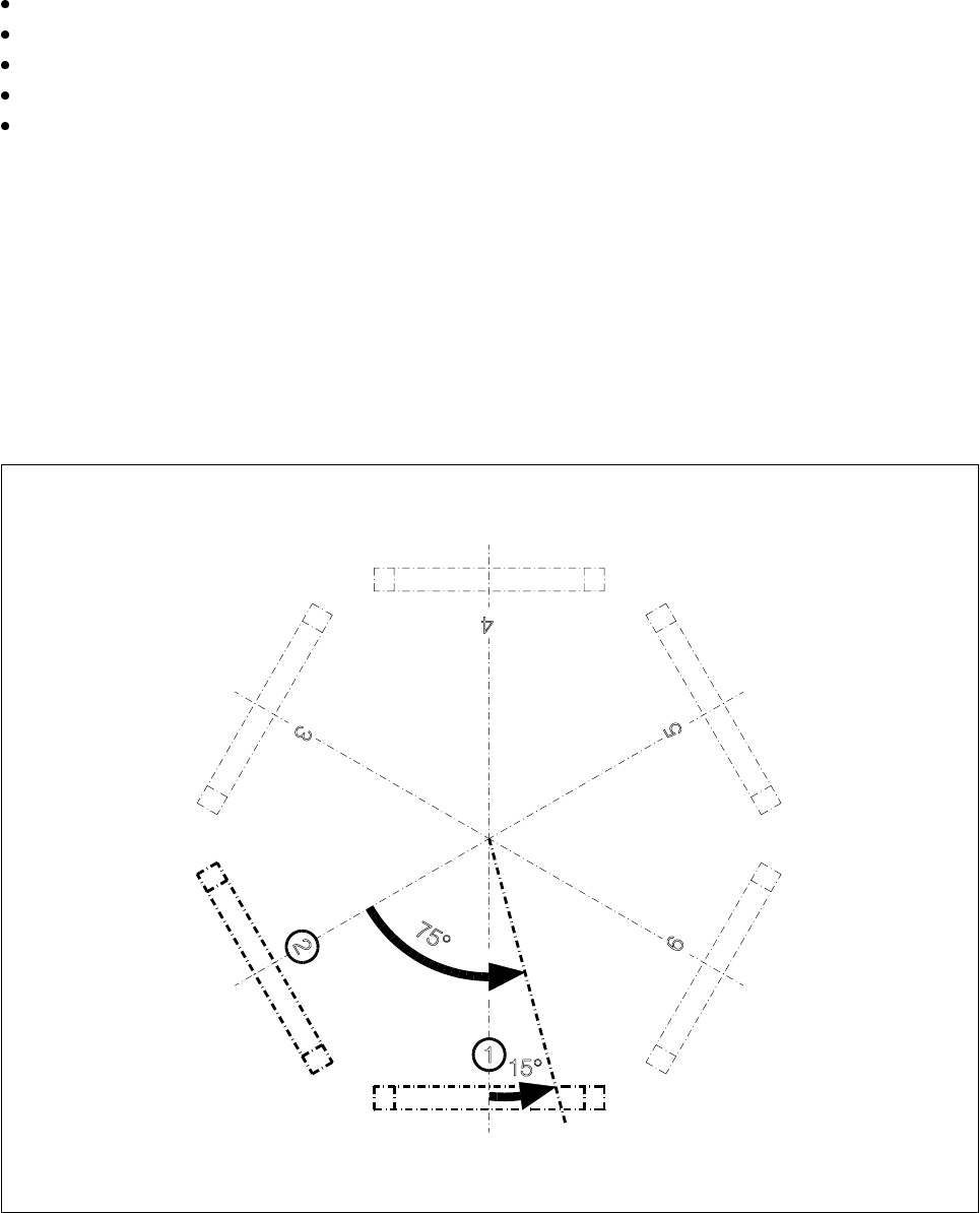
This valve adjustment drive is situated in star station 1 (see pos. 1, Fig. 9.7.8). Using your fingers, carefully
turn the star 15° counter-clockwise. 15° corresponds to a quarter turn of the star.
Fault prompted by the ’reject’ valve adjustment drive
This valve adjustment drive is situated in star station 3 (see pos. 3, Fig. 9.7.8). Using your fingers, carefully
turn the star 75° counter-clockwise. 75° corresponds to one and a half turns of the star.
Fig. 9.7.8 Positioning the star for valve plunger removal
- Key to Fig. 9.7.8
1 Position of the ’pick-up/place’ valve adjustment drive 3 Position of the ’reject’ valve adjustment drive
SIPLACE 80S-20/F4/F5 User Manual 9 Maintenance
05/99 Issue from Software Version SR.405.xx 9.7 6x Revolver Head (8000)
9 - 89
– To remove the valve plunger, it has to be in star position 1. You also have to be able to easily access the
valve plunger head with your fingers.
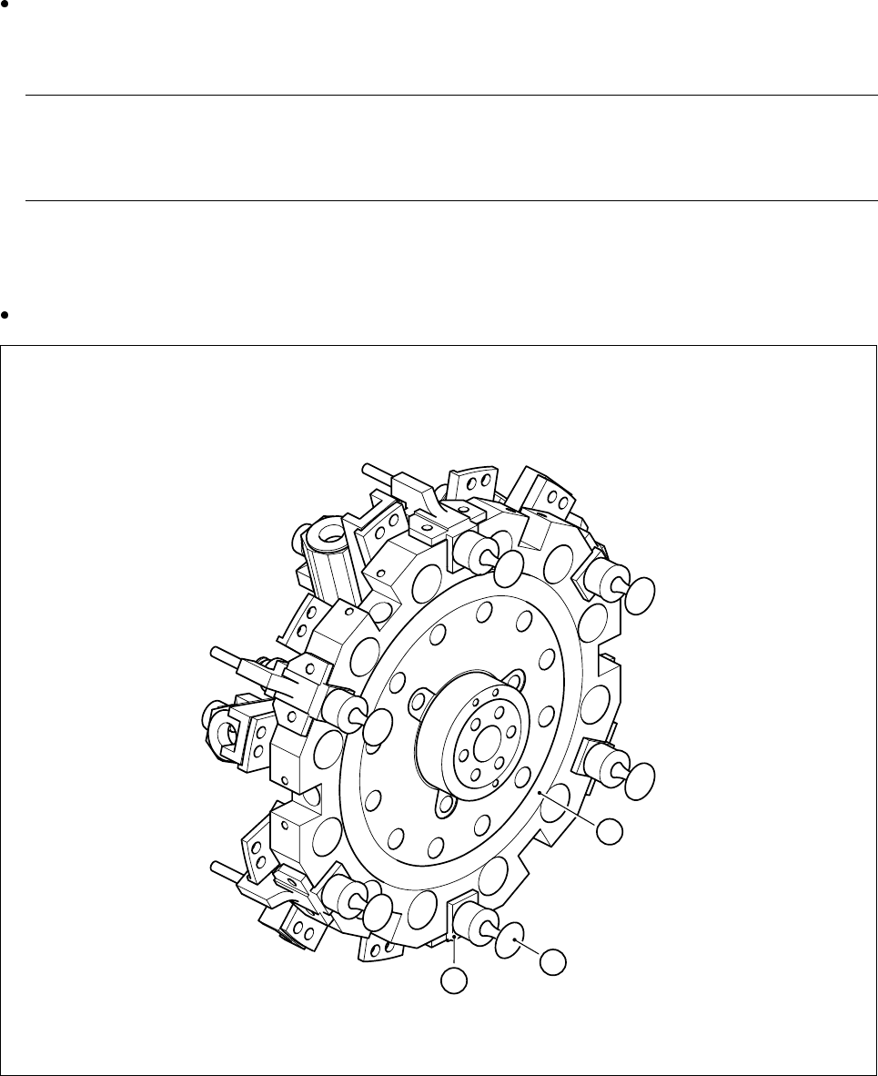
Take the valve plunger head3 (see Fig. 9.7.9) with your thumb and your forefinger and pull the valve
plunger out of the valve casing 2 (see Fig. 9.7.9). You will initially feel a slight resistance. The valve
plunger can then be pulled out easily.
NOTE
Do not use any pliers to pull out the valve plunger since this could damage the outside of the valve plunger
head.
9.7.6.2 Cleaning the Valve
Clean the hole in the valve casing 2 (see Fig. 9.7.9) with the plastic brush (
Ø 6)
.
Fig. 9.7.9 Star, complete
- Key to Fig. 9.7.9
1 Star, complete 2 Valve casing
3 Valve plunger
1
3
2