Portal-Operation-Manual-REV-I.pdf - 第40页
PVA Portal Manual Revision I / Janua ry 2022 Page 40 of 106 Figure 35 : System Tab 3. Select the “ Reset ” butt on to reset the cy cle count to zer o. 4. Select the “ Stop ” butto n to leave Setup mode and go to Cycle St…
PVA Portal Manual
Revision I / January 2022
Page 39 of 106
Setup Mode
The options shown in Portal depend on the workcell configuration. Refer to machine
specific manuals and appendices for more information.
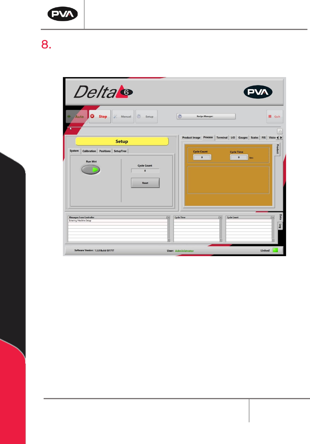
Figure 34: Setup Mode
In Setup mode, basic workcell functions can be controlled. Auto Cycle parameters and
some workcell parameters are set in Setup mode.
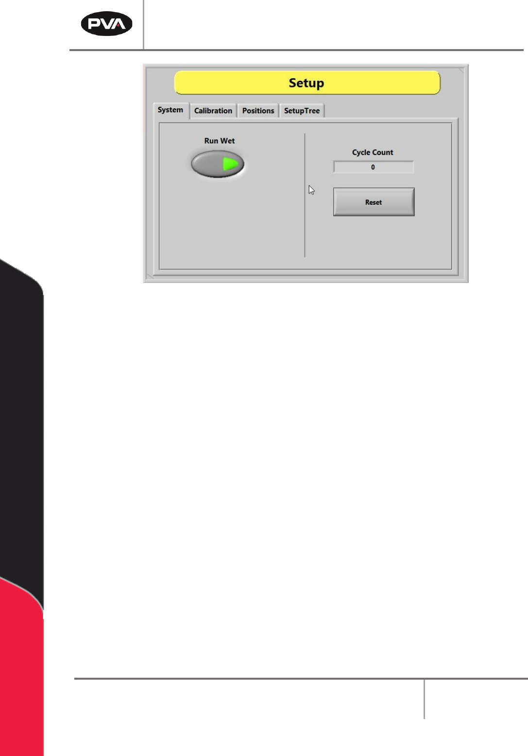
8.1 System
1. Select the “System” tab.
2. Select the “Run Wet” button to toggle it on or off. Valve operation is off for Auto
Cycle when the “Run Wet” button is set to off. This does NOT affect the run option
in the Manual mode. There is a separate option in Manual mode to select “Wet” or
“Dry”. Refer to Section 6.2 for more information.
PVA Portal Manual
Revision I / January 2022
Page 40 of 106
Figure 35: System Tab
3. Select the “Reset” button to reset the cycle count to zero.
4. Select the “Stop” button to leave Setup mode and go to Cycle Stop mode.
8.2 Calibration
The workcell has one of three calibration methods: Standard, Operator Defined, and
Sensor Defined.
If a Sensor Defined or Operator Defined method is installed on the workcell, the machine
may or may not automatically enter its particular calibration mode when entering Auto
mode. This will depend on which application the workcell was set up for. Refer to Section
8.2 for more information on different calibration sequences.
8.2.1 Standard Calibration
Standard Calibration is the easiest calibration procedure. Each head on the gantry will
have a set reference position. The operator can select the head and move the gantry to its
related position. When at the preset point, the operator must physically reposition the
dispense needle to confirm that the calibration is correct.
PVA Portal Manual
Revision I / January 2022
Page 41 of 106
Note: For a calibration plate, each valve tip should align with the crosshair center
point. If it does not, physically move the valve until it does. This is only for the
mechanical alignment of the head assembly.
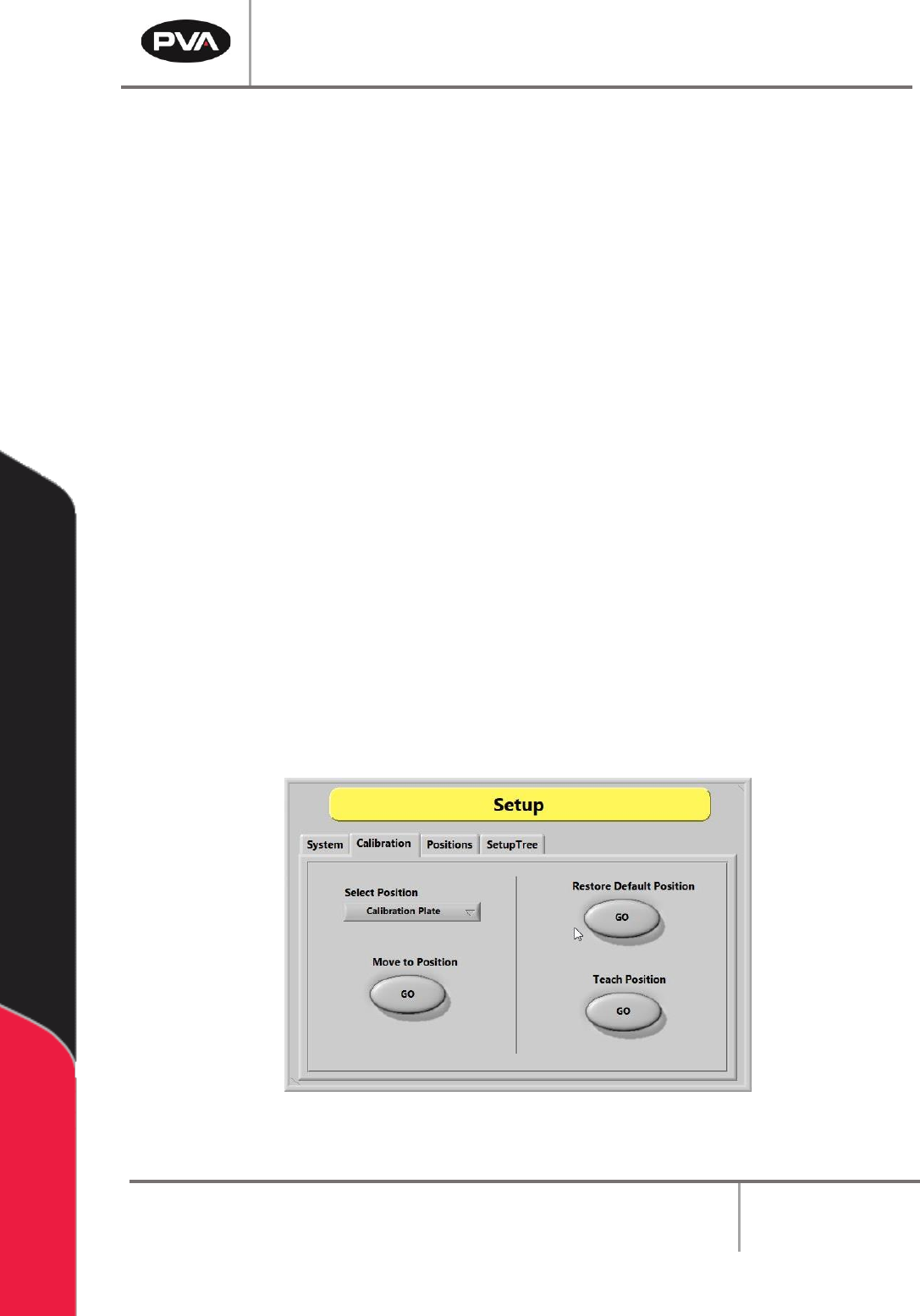
1. Select the “Calibration” tab in Setup mode.
2. Click the “Select Position” dropdown menu to change the active valve or tool.
3. Select the Move to Position - “GO” button to move the selected valve to the related
reference position. This procedure is useful when maintenance is performed that
might change the alignment of the gantry (e.g., replacing a valve after a head
collision).
4. Examine the position of the needle or calibration tip as it relates to the calibration
point (e.g., crosshairs).
5. If the needle or calibration tip is not directly above the point, manually bend the
needle or adjust the tool position so that the needle or calibration tip is above the
calibration point.
6. Select the Restore Default Position - “GO” button to restore the calibration
position back to factory defaults.
7. Select the Teach Position – “GO” button to reteach the predefined calibration
reference position. Use the Teach Pendant to move the desired tool to the
calibration plate. If installed, press “PURGE” to toggle the pneumatic Z-slide up or
down. Press “TEACH” to save the position.
Figure 36: Calibration Tab in Setup Mode
Refer to pump specific manuals for more information.