Portal-Operation-Manual-REV-I.pdf - 第93页
PVA Portal Manual Revision I / Janua ry 2022 Page 93 of 106 3. Select the “ Continue ” button. 4. Refer to the Pneumatic Actua tor Failure sec tion in the Work cell Install ation Guidelines Troubl eshooting M aintenance …
PVA Portal Manual
Revision I / January 2022
Page 92 of 106
15.3 Resetting the Exhaust Fan Overload Relay
Machines with exhaust fans may have errors if the overload relays trip. Perform the
following steps to return to normal operation:
1. Set the main power switch to the “OFF” position.
2. Open the electrical enclosure and examine the overload relay for a tripped flag.
3. Confirm that the current set point is set correctly on the overload relay. Examine
the rating on the exhaust fan housing for current draw.
4. If necessary, push the “Reset” button to reset the relay.
5. Restart the machine.
6. If the problem persists, refer to the Workcell Installation Guidelines Troubleshooting
Maintenance Manual or contact PVA Customer Service for more information.
15.4 Pneumatic Error Recovery Procedure
The system’s pneumatics are checked for errors every time they operate. The pneumatics
must be in their home position before the axes can home or move to the standby position.
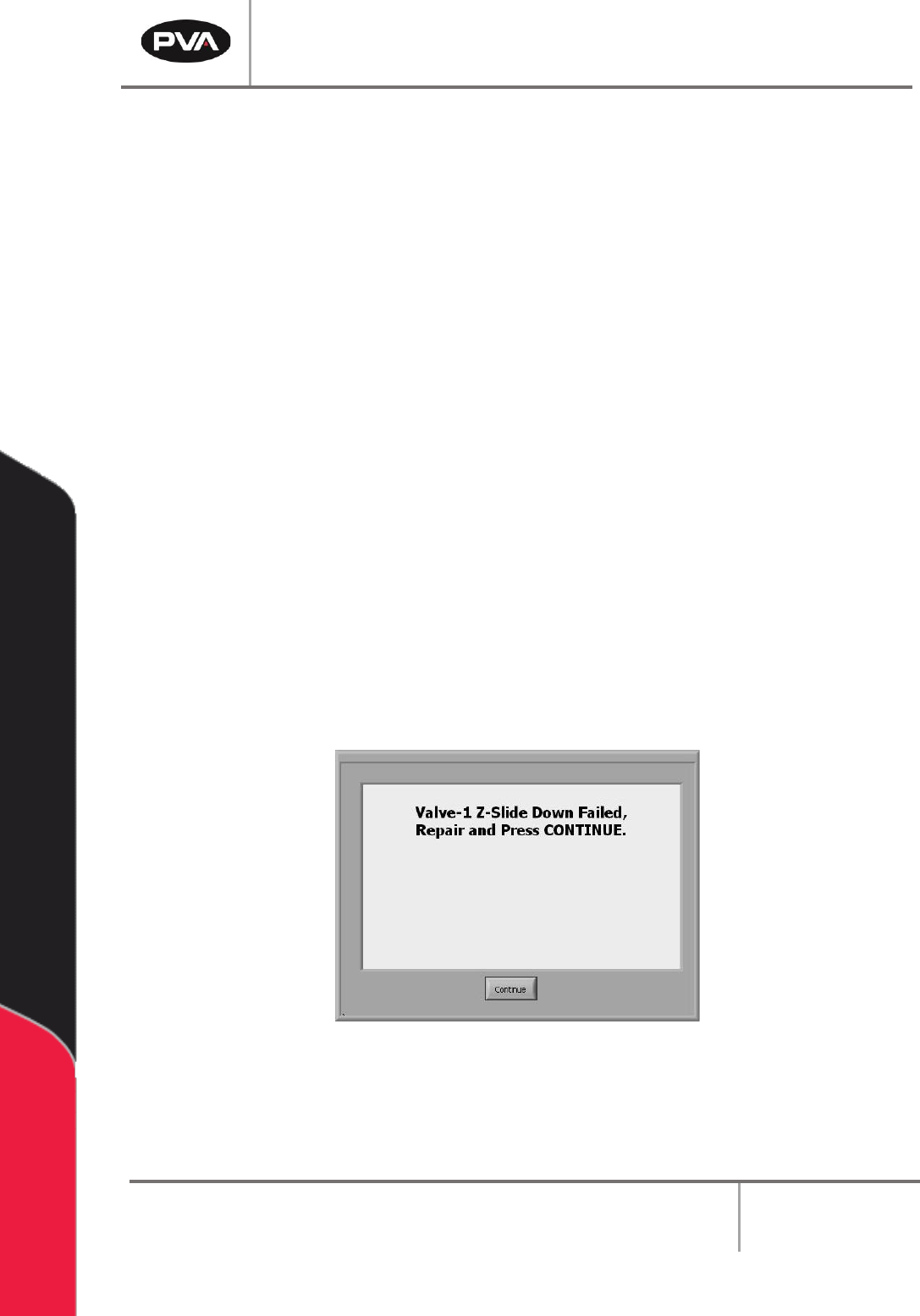
If a pneumatic fails, an error will be shown.
Figure 118: Pneumatic Error Example
1. Find the cause of the problem.
2. Correct the problem.
PVA Portal Manual
Revision I / January 2022
Page 93 of 106
3. Select the “Continue” button.
4. Refer to the Pneumatic Actuator Failure section in the Workcell Installation
Guidelines Troubleshooting Maintenance Manual for more information.
15.5 Run-Time Error Recovery Procedure
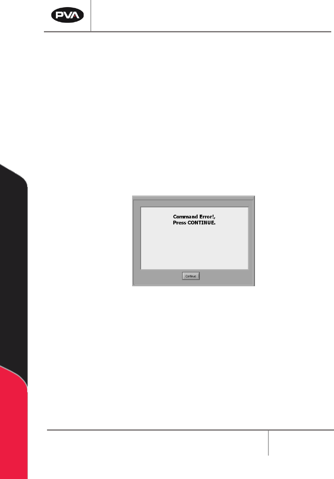
Run-time errors are generated during the operation of a program. This type of failure
should not occur during normal operation. The error type and program line number will be
displayed in the system messages window.
1. Find and record the error type, program line number, and any additional information
shown in the system messages window and contact PVA Technical Support.
2. Select the “Continue” button.
Figure 119: Command Error Example
3. Perform the Startup/Recovery Procedure. Refer to Section 15.1 for more
information.
4. Download the updated program and run it to confirm if the error was corrected.
Note: For more information on error codes, refer to the Troubleshooting guide. For
more information on programming paths, refer to the PathMaster® manual.
PVA Portal Manual
Revision I / January 2022
Page 94 of 106
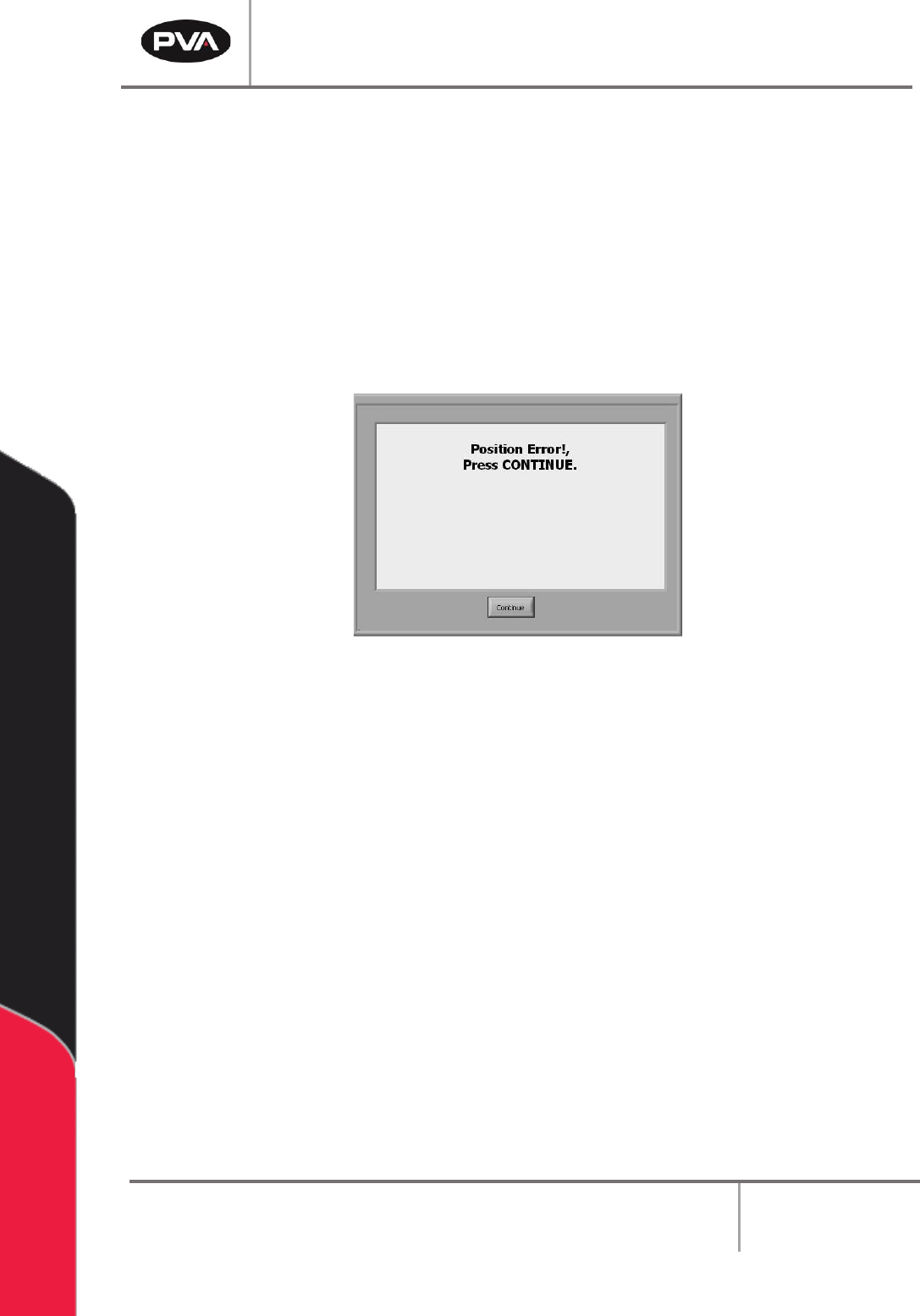
15.6 Position Error Recovery Procedure
A position error occurs when the difference between the commanded position and the
current position is more than the maximum allowable error limit for an axis.
An error limit will happen if the dispense/spray head hits a hard stop in Manual mode, if the
speed or acceleration is set too high, or if the axes drives are not powered. Ensure the
“Emergency Stop” button is not engaged. The motor stop codes are shown in the system
messages window.
Note: Refer to Section 15.8 for more information on stop codes.
Figure 120: Position Error
To correct the position error, perform the following steps:
1. Engage the “Emergency Stop” button.
2. Open the access door.
3. Move the dispense head to the center of the work area. Engage the brake on the Z-
axis. Turn the Z-axis motor coupling by hand to move the dispense head, as
necessary.
4. Close the access door.
5. Disengage the “Emergency Stop” button.
6. Select the “Continue” button to clear the error.
7. Perform the Startup Procedure. Refer to Section 10.1 for more information.