Portal-Operation-Manual-REV-I.pdf - 第67页
PVA Portal Manual Revision I / Janua ry 2022 Page 67 of 106 10.1.1 Portal Shell 1. Ensure the computer connecte d to the workc ell is turned on. 2. Porta l Shell will open an d provide a list of op tions. 3. Select the “…
PVA Portal Manual
Revision I / January 2022
Page 66 of 106
Operation
Note: Administrator level privileges are needed to setup and correctly configure the
workcell. Additionally, Windows® User Account Control must be turned off.
10.1 Startup Procedure
Note: Do not power on the workcell or add material to the pressure vessels until they
are properly grounded.
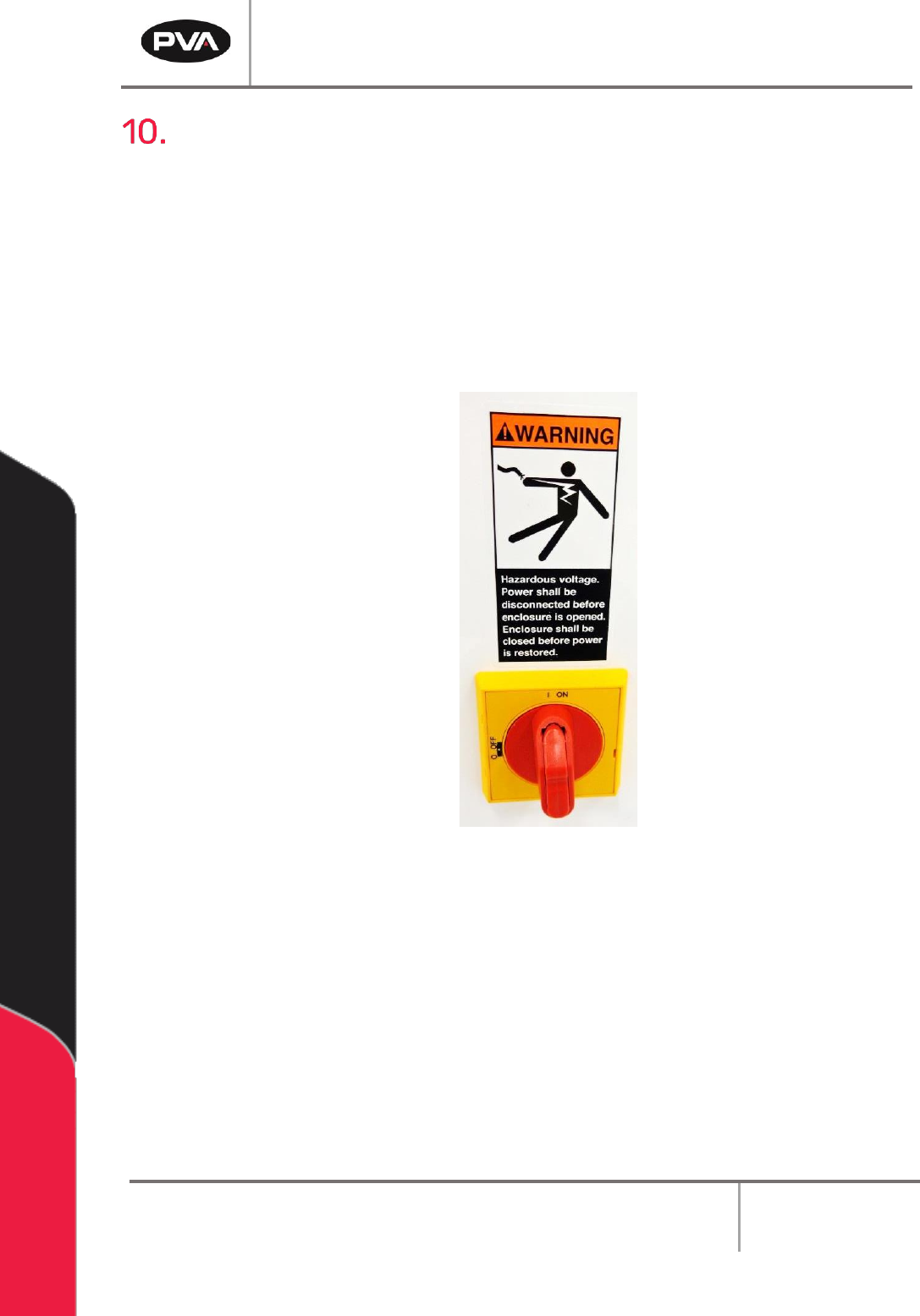
1. Turn the main power switch to the “ON” position.
Figure 68: Main Power Switch Example
2. Ensure both the fluid and air pressures are in the correct pressure range.
3. Close all the doors.
4. If applicable, turn the “DOOR BYPASS” key switch to the “OFF” position.
5. Engage the “Emergency Stop” button.
6. Turn the main power switch to the “ON” position.
PVA Portal Manual
Revision I / January 2022
Page 67 of 106
10.1.1 Portal Shell
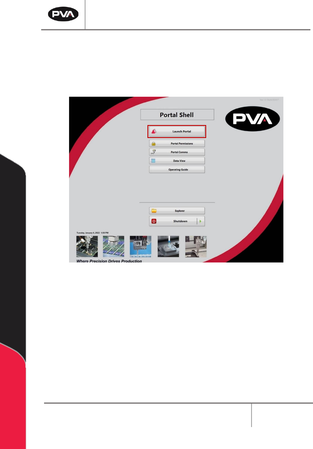
1. Ensure the computer connected to the workcell is turned on.
2. Portal Shell will open and provide a list of options.
3. Select the “Launch Portal” button to open Portal.
Figure 69: Portal Shell
PVA Portal Manual
Revision I / January 2022
Page 68 of 106
10.1.2 Login to Portal
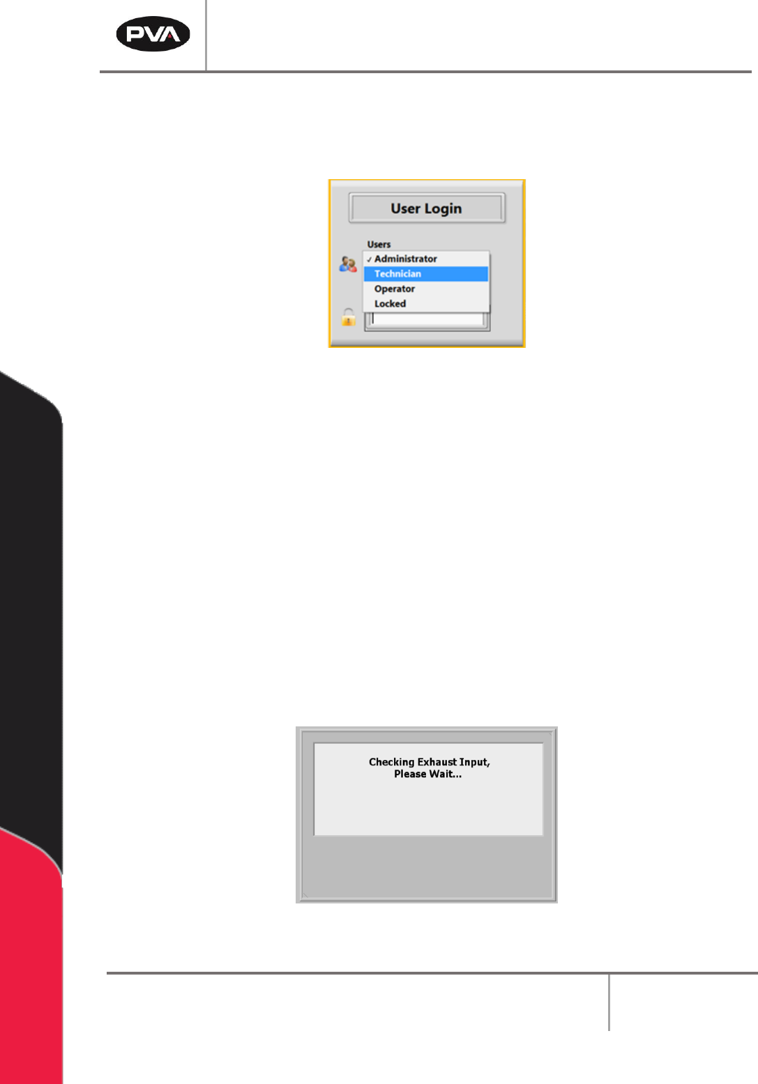
Login to the PVA Portal Software by selecting the correct user and entering the
corresponding password. Push the “Enter” button on the keyboard.
Figure 70: User Selection
Note: PVA configures the default password as blank. Refer to Section 11 for more
information on Portal Permissions.
10.2 Exhaust Verification
Once the workcell has initialized, it will perform an Exhaust Verification test of the
exhaust flow rate. If initialization fails, refer to the workcell manual for fault diagnostics.
The exhaust flow rate is monitored with the on-board pressure differential switch.
The workcell must exhaust at a rate no less than 300 cubic feet per minute (CFM),
otherwise a critical fault will occur and stop the motors. The Exhaust Verification test will
also help to evacuate any vapors that are in the work area. The time this takes is based on
the CFM and the area that must be evacuated. The Exhaust Input Screen below will be
shown:
Figure 71: Exhaust Input Screen