Portal-Operation-Manual-REV-I.pdf - 第54页
PVA Portal Manual Revision I / Janua ry 2022 Page 54 of 106 8.4.8.5 Flow Monitor Calibrati on The Flow Monito r on the wor kcell measure s the amou nt of material that mov es through the material sup ply line befor e it …

PVA Portal Manual
Revision I / January 2022
Page 53 of 106
7. In the SetupTree tab, adjust the setpoint to match the value found.
8. Change the flow set point to the value that was shown on the mode system
messages window. This will be a DMC command in the path program; adjust the
value of the variable to achieve this.
9. Select the “Stop” button to go to Cycle Stop mode.
10. Select Manual mode.
11. Operate the workcell for additional cycles to ensure that the path program
dispenses the same amount of material for each cycle.
8.4.8.3 Set the Material Volume Check
The settings for the material volume check must be programmed into the path program. If
no settings are programmed in the path, the machine will use the flow monitor settings of
the most recently run program. To set the material volume check parameters, program the
following settings into the path program using the two variables FCx_SET and FCx_DEV:
Note: If either of these variables are set to “0”, they will cause errors.
• “x” is the letter of the related flow monitor (A, B, C, or D).
• FCx_SET is the set point for the material flow in cc.
• FCx_DEV is the percent deviation permitted, which can range from 0 to 99.
For example, entering the following line into a path program would put the volume setting
for monitor ‘A’ at 0.5 cc and the allowable deviation at 5%:
• FCA_SET=0.500; FCA_DEV=5
8.4.8.4 Auto Cycle Flow Error
Auto Cycle checks the material flow after every cycle if the error is turned “ON” in Flow
Control mode. If the volume is within the set parameters, no indication is shown. When the
volume is outside the set parameters, the flow error screen is shown when the cycle
completes, not immediately on error. Before operating the workcell again, remove the part.
Note: Any changes made to settings in the material delivery system (material
pressure, stroke adjustment, etc.) will affect the data from the flow monitor. When
this happens, it will be necessary to find the correct material volume again.

PVA Portal Manual
Revision I / January 2022
Page 54 of 106
8.4.8.5 Flow Monitor Calibration
The Flow Monitor on the workcell measures the amount of material that moves through
the material supply line before it splits to supply individual valves. It does not control the
process, but reports deviations from the set values. Both the necessary material volume
and the permitted deviation are determined by the operator. The flow monitor calibration
should be examined once a month or if changes are made to the fluid delivery system.
The following procedure is to calibrate a single flow monitor, if the specific gravity of the
dispensed material is known. This procedure would calibrate the A flow monitor, to
calibrate the B, C, and D monitors replace the variable DEZ, with DEW, DEE, and DEF as well
as FCA_CAL, with FCB_CAL, FCC_CAL, and FCD_CAL, respectively. Refer to Table 1 for
more information on the variables relating to each flow monitor.
1. Login to Portal.
2. Ensure the workcell is in Manual mode.
3. Select the Terminal tab on the right side of the Portal screen to open the terminal.
4. Type DEZ=0 (for first flow monitor only) in the top of the terminal screen and select
the “Enter” button on the keyboard. This resets the flow monitor encoder to zero.
5. Weigh an empty purge cup and record the weight or zero the scale with the empty
purge cup on it.
6. Purge a quantity of material into the purge cup.
7. Type DEZ=? into the terminal and select the “Enter” button on the keyboard. A
number will return (e.g., 50 counts per cc dispensed). The factory set value is 1000
count/cc. If zeros or incorrect data are returned, type MG_DEZ=?
8. Weigh the dispensed quantity of material in grams. If necessary, subtract the weight
of the cup from this value.
9. To find the material volume in cc, use the equation below:
Grams of material/specific gravity = cc
e.g.: 0.500 g/0.96 = 0.5208 cc
10. Use this value (in cc) to find the correct number of counts per cc dispensed.
Counts/cc = counts per cc
e.g.: 25 counts/0.5208 cc = 48.003 counts per cc
PVA Portal Manual
Revision I / January 2022
Page 55 of 106
11. Repeat this procedure at least three times then average the results.
12. Open the Main Program in a text editor such as Windows® NotePad.
13. Search for the variable: FCA_CAL=. This will be in the section titled: REM !!!!
Machine-Specific Information!!!!
14. Type in the new value for FCA_CAL= (e.g.: FCA_CAL=48.003).
15. Download the modified main program and test changes.
Flow Monitor
Variables
A
DEZ
FCA_CAL
B
DEW
FCB_CAL
C
DEE
FCC_CAL
D
DEF
FCD_CAL
Table 1: Flow Monitor Variables
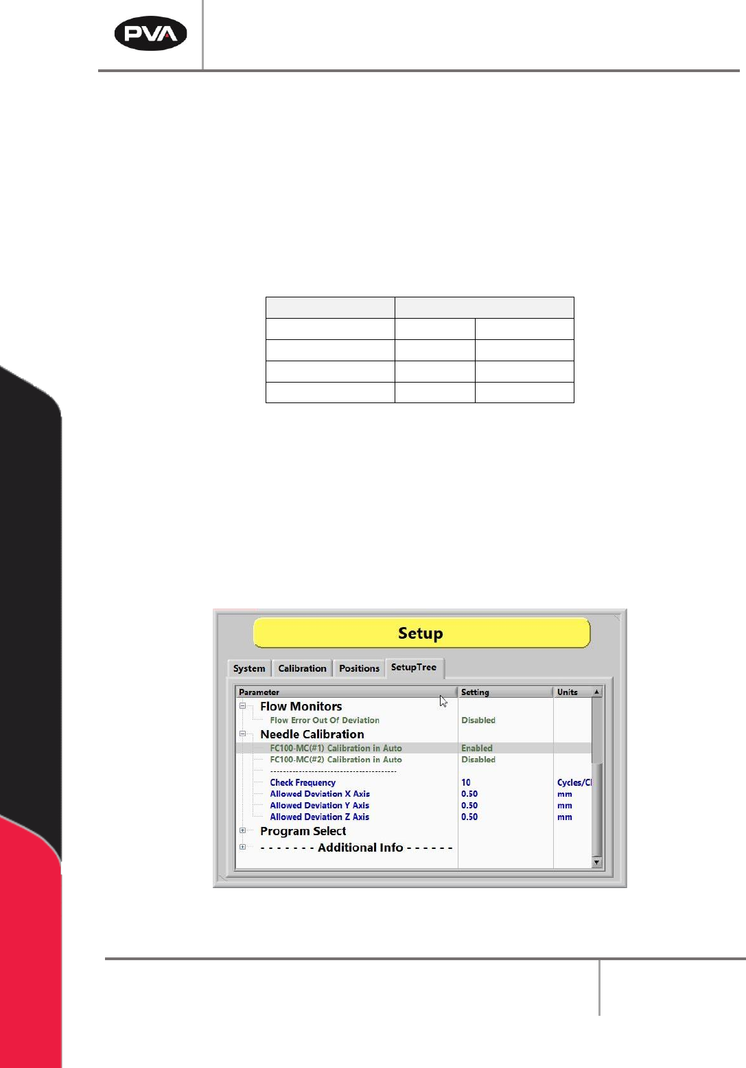
8.4.9 Needle Calibration
If the system is equipped with the Needle Calibration Sensor Block, refer to Figure 37.
Needle Calibration can be set to run in Auto Cycle. A list of tools will be listed along with
the option to enable or disable this function. The check frequency is the number of cycles
run per check. The allowable deviation can be set for the X, Y, and Z axis in mm.
Figure 51: Enable or Disable Tools for Needle Calibration