Portal-Operation-Manual-REV-I.pdf - 第88页
PVA Portal Manual Revision I / Janua ry 2022 Page 88 of 106 14.3.1 Train Part Faults There are two typ es of faul ts that can occur when training a part: 1. Train Part Timeo ut : A timeout f ault that occur s when the us…
PVA Portal Manual
Revision I / January 2022
Page 87 of 106
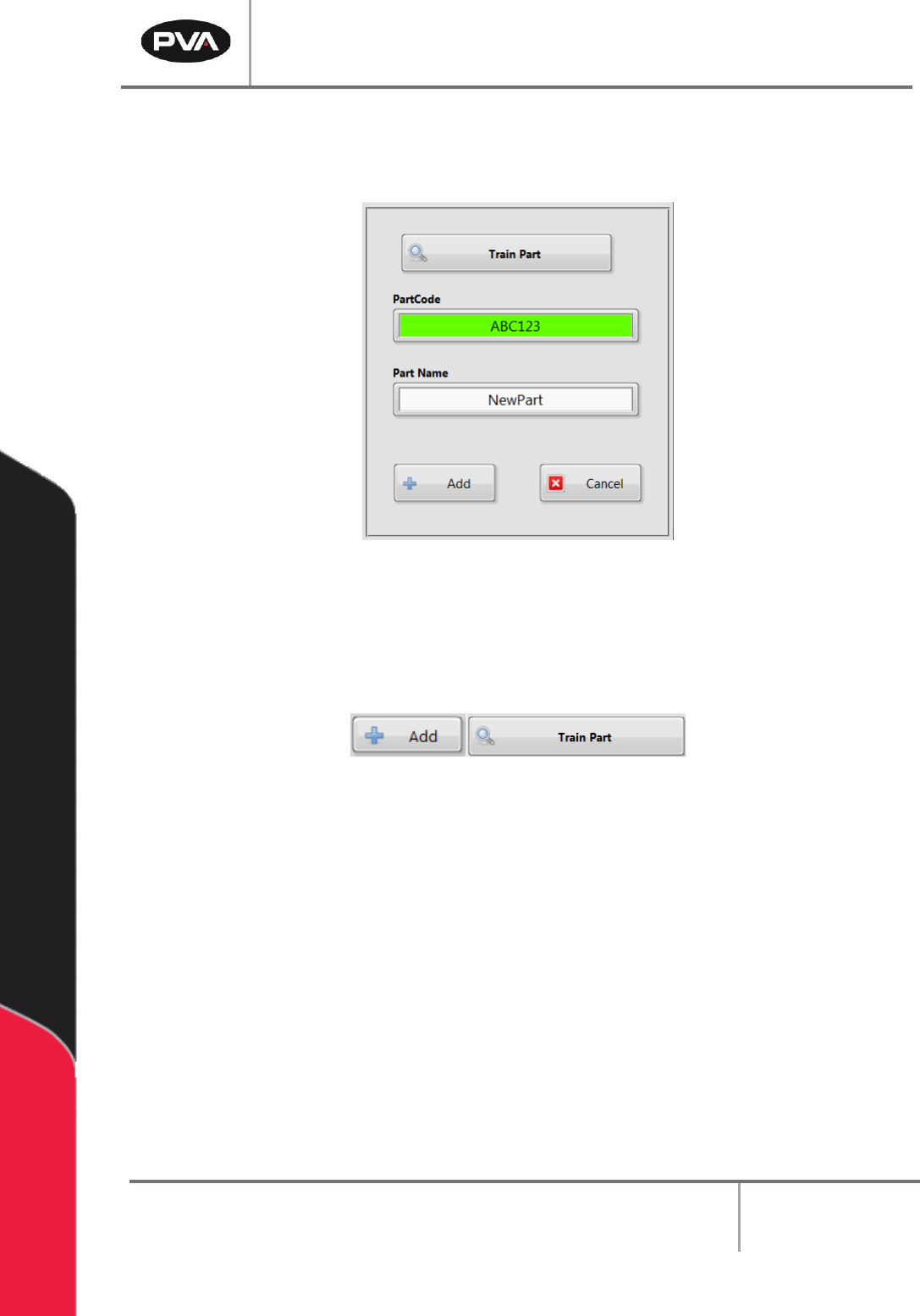
4. After the PartCode is read, the value is shown in the PartCode field.
5. Enter a unique part name in the Part Name field.
Figure 111: Train Part Window
6. Click the “Add” button to add the new part to the dataset or click the “Train Part”
button to train the PartCode.
Figure 112: Add and Train Part Buttons
Note: If an error needs to be corrected in the PartCode scanned, or if the PartCode
scan was incomplete, select the “Train Part” button.
PVA Portal Manual
Revision I / January 2022
Page 88 of 106
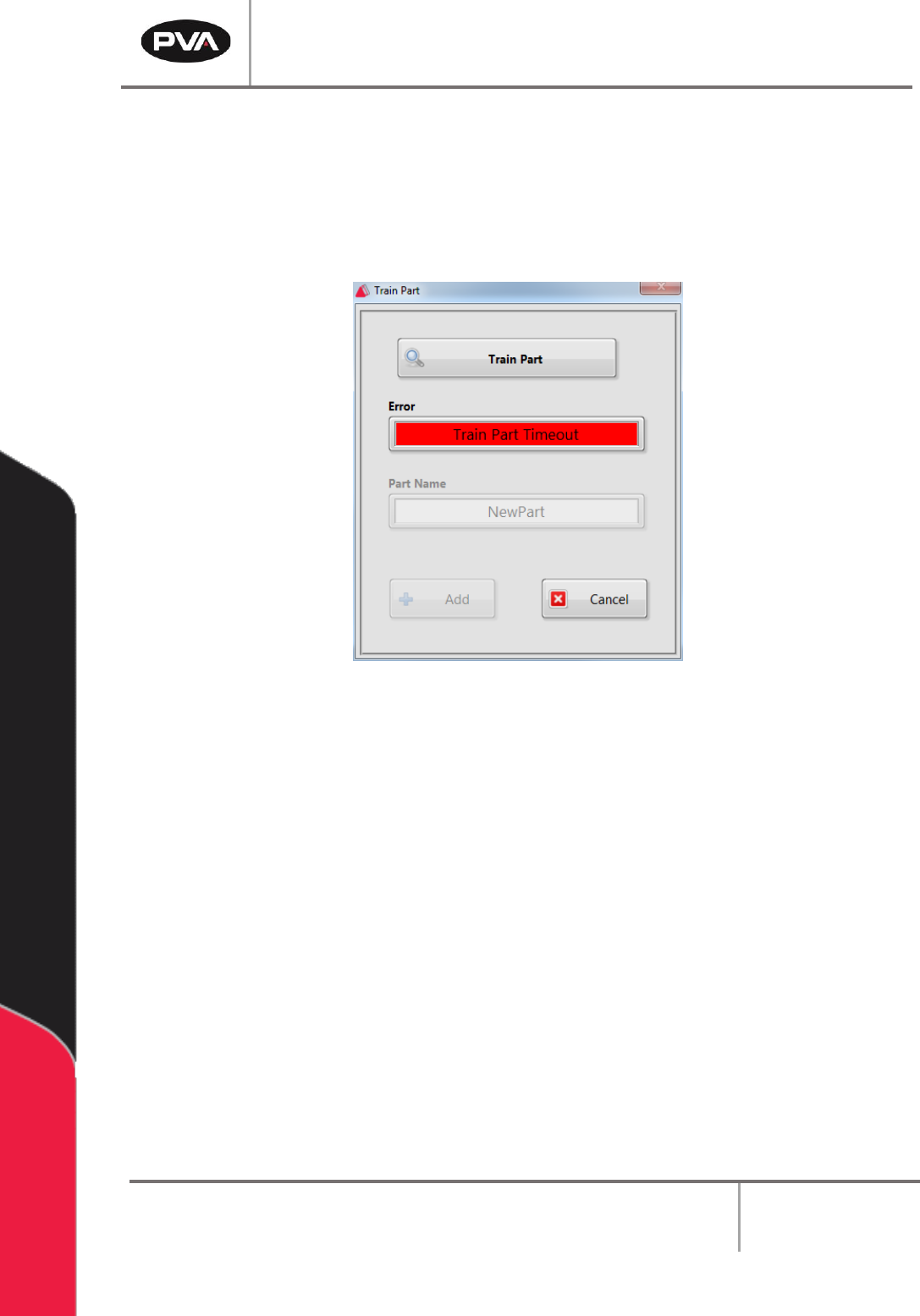
14.3.1 Train Part Faults
There are two types of faults that can occur when training a part:
1. Train Part Timeout: A timeout fault that occurs when the user clicked the “Train
Part” button to request a PartCode, but the system did not respond within the 10
second timeout period.
Figure 113: Train Part Timeout Error
2. Train Part Failed: This fault occurs when the system returns a Negative
Acknowledge (NAK) when asked to read the PartCode. This means that the device
could not successfully read the PartCode.
PVA Portal Manual
Revision I / January 2022
Page 89 of 106
Faulty Recovery
15.1 Recovering From Emergency Stop and Other
Machine Errors
If the Emergency Stop button is engaged or the machine encounters a system error,
perform the following procedure to return the machine back to normal operation.
Note: If the Emergency Stop was engaged because of system failure, DO NOT
disengage the Emergency Stop button. Shut the system down and have qualified
personnel repair the machine. Do not operate the workcell again until the cause of
the failure has been repaired.
1. Open the front doors and remove all parts/PCBs from the work area.
2. Close the doors and disengage the “Emergency Stop” button if it was not engaged
because of a system failure.
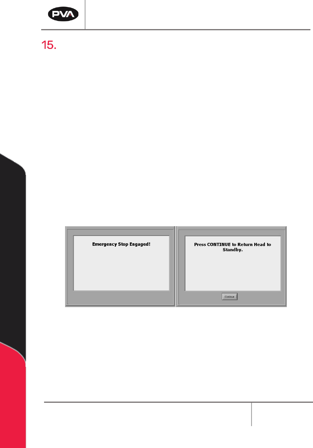
3. Press the “Continue” button to return the head to the Standby Position. The
screen will return to the Cycle Stop mode.
Note: All functions are stopped until the “Emergency Stop” button is disengaged.
Figure 114: Emergency Stop Screens
4. Correct the fault that caused the operator to engage the “Emergency Stop” button.
5. Open the access door.
6. Remove all parts from the work area. Find any parts that can still be used and put
them in the input queue.
7. Close the access door.