Portal-Operation-Manual-REV-I.pdf - 第42页
PVA Portal Manual Revision I / Janua ry 2022 Page 42 of 106 8.2.2 Sensor Defined Tool Ca libration The sensor defin ed tool calibration block consists of three sensors with one for each axis (X,Y, and Z). Figure 37 : Too…
PVA Portal Manual
Revision I / January 2022
Page 41 of 106
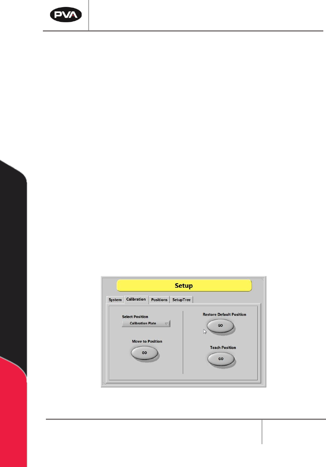
Note: For a calibration plate, each valve tip should align with the crosshair center
point. If it does not, physically move the valve until it does. This is only for the
mechanical alignment of the head assembly.
1. Select the “Calibration” tab in Setup mode.
2. Click the “Select Position” dropdown menu to change the active valve or tool.
3. Select the Move to Position - “GO” button to move the selected valve to the related
reference position. This procedure is useful when maintenance is performed that
might change the alignment of the gantry (e.g., replacing a valve after a head
collision).
4. Examine the position of the needle or calibration tip as it relates to the calibration
point (e.g., crosshairs).
5. If the needle or calibration tip is not directly above the point, manually bend the
needle or adjust the tool position so that the needle or calibration tip is above the
calibration point.
6. Select the Restore Default Position - “GO” button to restore the calibration
position back to factory defaults.
7. Select the Teach Position – “GO” button to reteach the predefined calibration
reference position. Use the Teach Pendant to move the desired tool to the
calibration plate. If installed, press “PURGE” to toggle the pneumatic Z-slide up or
down. Press “TEACH” to save the position.
Figure 36: Calibration Tab in Setup Mode
Refer to pump specific manuals for more information.
PVA Portal Manual
Revision I / January 2022
Page 42 of 106
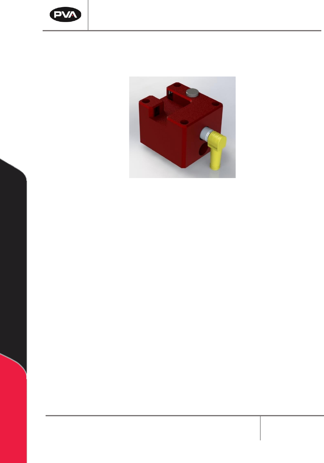
8.2.2 Sensor Defined Tool Calibration
The sensor defined tool calibration block consists of three sensors with one for each
axis (X,Y, and Z).
Figure 37: Tool Calibration Sensor Block
Refer to the PathMaster® Manual for more information.
Warning: Do not unplug the cable from the calibration block while the system is
powered on, as this could damage the sensors and/or motion controller.
PVA Portal Manual
Revision I / January 2022
Page 43 of 106
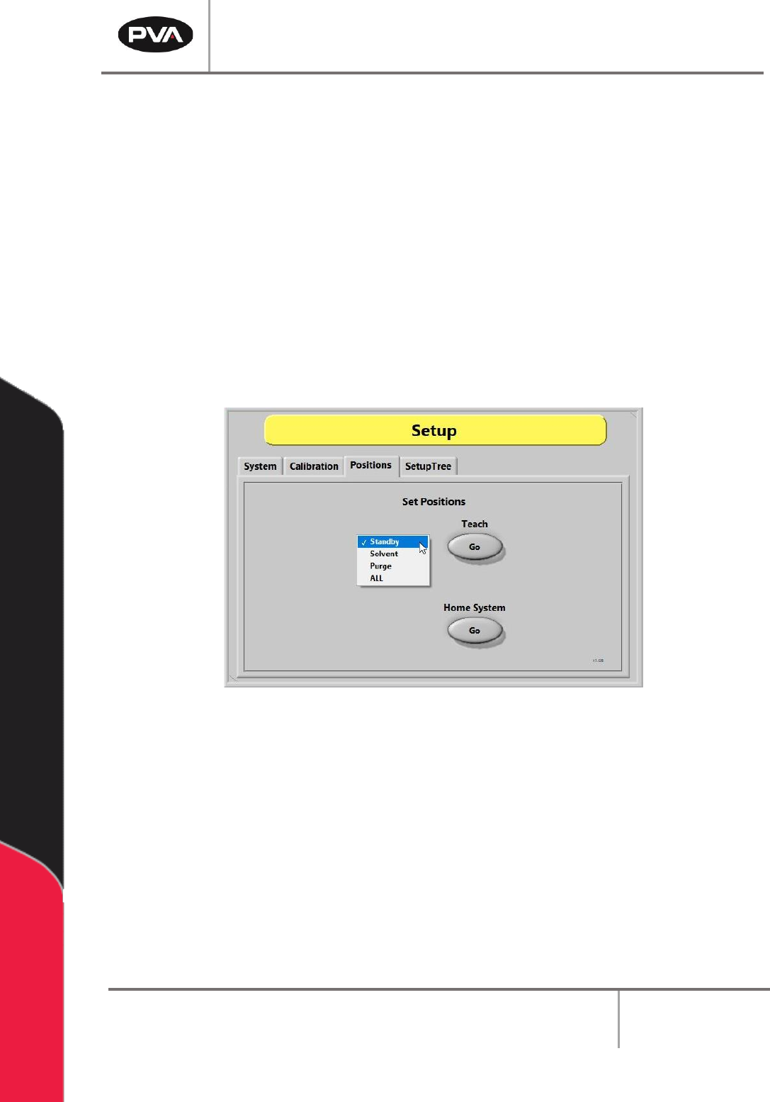
8.3 Positions
To re-teach the Park/Idle Positions:
1. Select the appropriate position option (e.g., Standby, Solvent, Purge, or ALL).
2. Select the Teach – “Go” button.
3. While using the Teach Pendant/Trackball, move the head to the desired position. If
pneumatic Z-slides are installed, press and hold the Purge button to drop them for
teaching the solvent and purge positions.
4. Press the “Teach” button when finished to save the new position.
5. To re-home the system, press the Home System – “Go” button.
Figure 38: Positions Tab