Portal-Operation-Manual-REV-I.pdf - 第51页
PVA Portal Manual Revision I / Janua ry 2022 Page 51 of 106 8.4.7 FIS In the FIS option of the Setup Tree tab, the FIS Communicati on can be either enabled or disabled. Refer to Section 6.8 for mor e informa tion on FIS.…
PVA Portal Manual
Revision I / January 2022
Page 50 of 106
When enabled, the Run Camera Live function will make the camera live unless an
inspection is running or if there is a failed inspection. If disabled, the camera will run live
only during the inspection and then turn off.
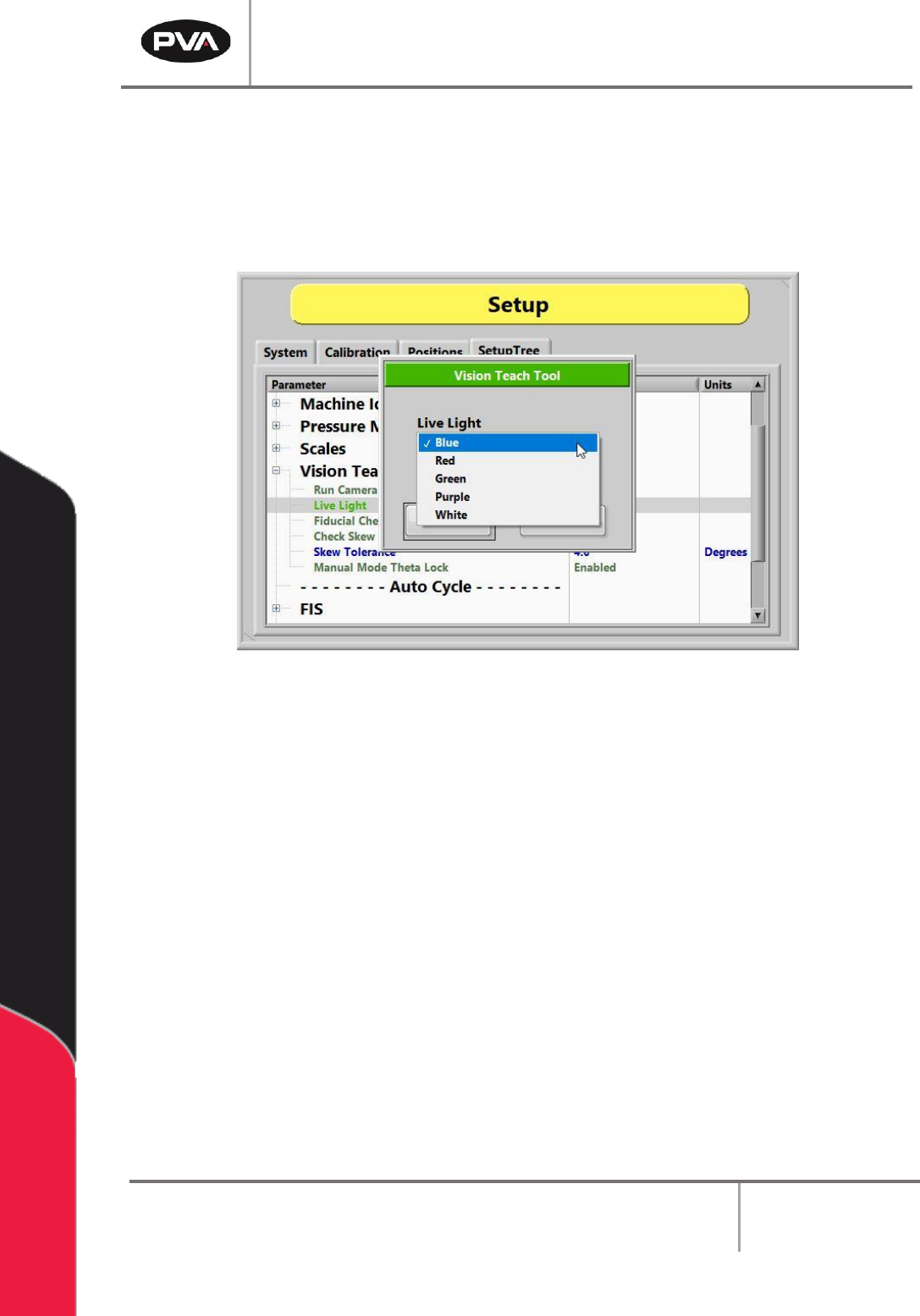
The Live Light function allows the live light color to be changed to blue, red, green, purple,
or white.
Figure 49: Vision Teach Tool Live Light Options
When the Fiducial Check function is enabled, a fiducial check will run in Auto Cycle. When
the function is disabled, the camera will go to the fiducial coordinate but will not run the
inspection.
Note: Any lights related to the inspection will shut off when the camera is not live.
If enabled, the Check Skew mode will apply a skew correction to the current program.
The Skew Tolerance is the allowable skew correction value in degrees. The range is 0 to 7
degrees of rotation.
The Manual Mode Theta function unlocks the theta position (W-axis) to prevent teaching
an incorrect theta position.
PVA Portal Manual
Revision I / January 2022
Page 51 of 106
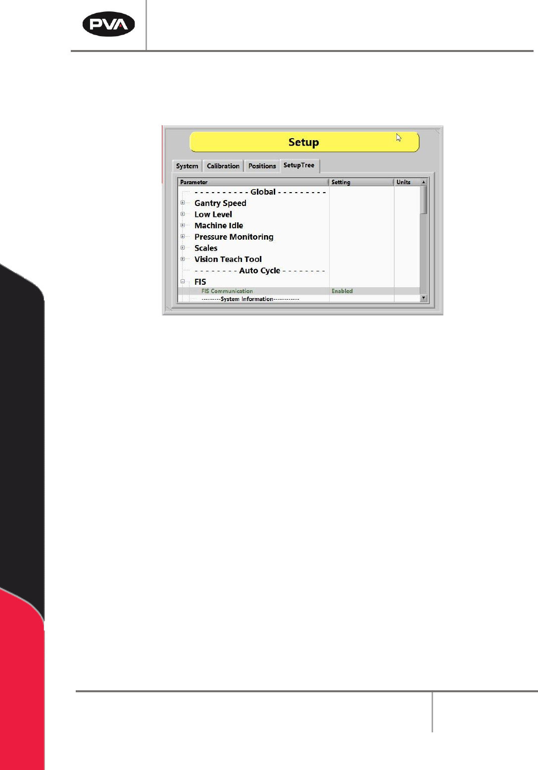
8.4.7 FIS
In the FIS option of the SetupTree tab, the FIS Communication can be either enabled or
disabled. Refer to Section 6.8 for more information on FIS.
Figure 50: Enable or Disable FIS
8.4.8 Flow Monitors
The Flow Monitor will always be in the SetupTree with only on/off settings. The Setpoint
and Deviation MUST be set in path programs.
Some workcells have flow monitors, up to four, installed. Workcell flow monitors measure
the amount of material that flows through the supply line before it goes to supply the
individual valves. Flow monitors are used to show when the actual values are outside of the
set values. The operator sets the necessary material volume and a permitted deviation.
8.4.8.1 Priming the Flow Monitor
The flow monitor must be primed before it is used to prevent damage. When priming the
flow monitor, the amount of air that goes through the unit during the initial startup is
reduced. Perform the following procedure to prime the flow monitor:
1. Fill the pressure vessel with material and close tightly. Refer to the system manual
for more information.
2. Set the material pressure regulator to 0 psi.
3. Turn the air inlet and the material outlet valves to the closed position.

PVA Portal Manual
Revision I / January 2022
Page 52 of 106
4. Disconnect the material line from the inlet port of the flow monitor.
5. Turn the air inlet and the material outlet valves to the open position.
6. Use the material pressure regulator to slowly increase the material pressure until
material flows from the disconnected material line.
7. Turn the material outlet valve to the closed position.
8. Reduce the pressure for the pressure vessel and adjust the material pressure
regulator to 0 psi. Refer to the fluid system manual for more information.
9. Reconnect the material line to the inlet port of the flow monitor.
10. Perform the manual purge procedure to open the valves. Refer to Section 6.1 for
more information.
11. Turn the material outlet valve to the open position.
12. Use the material pressure regulator to slowly increase the material pressure to the
operating pressure.
13. Repeat the manual purge procedure for each valve until the material flows without
any breaks in the flow.
8.4.8.2 Finding the Correct Material Volume
A complete path program is needed before being able to find the correct material volume.
Any change to a program also changes the flow data results.
1. Load a completed path program into memory.
2. In Portal, select Manual mode.
3. Put the board in the correct position, as related to the board stops, and run one
cycle as “WET”. For more information on Manual mode, refer to Section 6.
4. After the cycle is completed, the dispensed volume is shown in the system
messages window.
5. Select the “Stop” button to go to Cycle Stop mode.
6. Select Setup mode and then the “Flow Monitor” tab.