Portal-Operation-Manual-REV-I.pdf - 第47页
PVA Portal Manual Revision I / Janua ry 2022 Page 47 of 106 8.4.3 Machine Idle Using the Machine Idle opti on, the purg e and/or solvent cup features can be adju sted . Auto purge disp enses mat erial from all valve s at…
PVA Portal Manual
Revision I / January 2022
Page 46 of 106
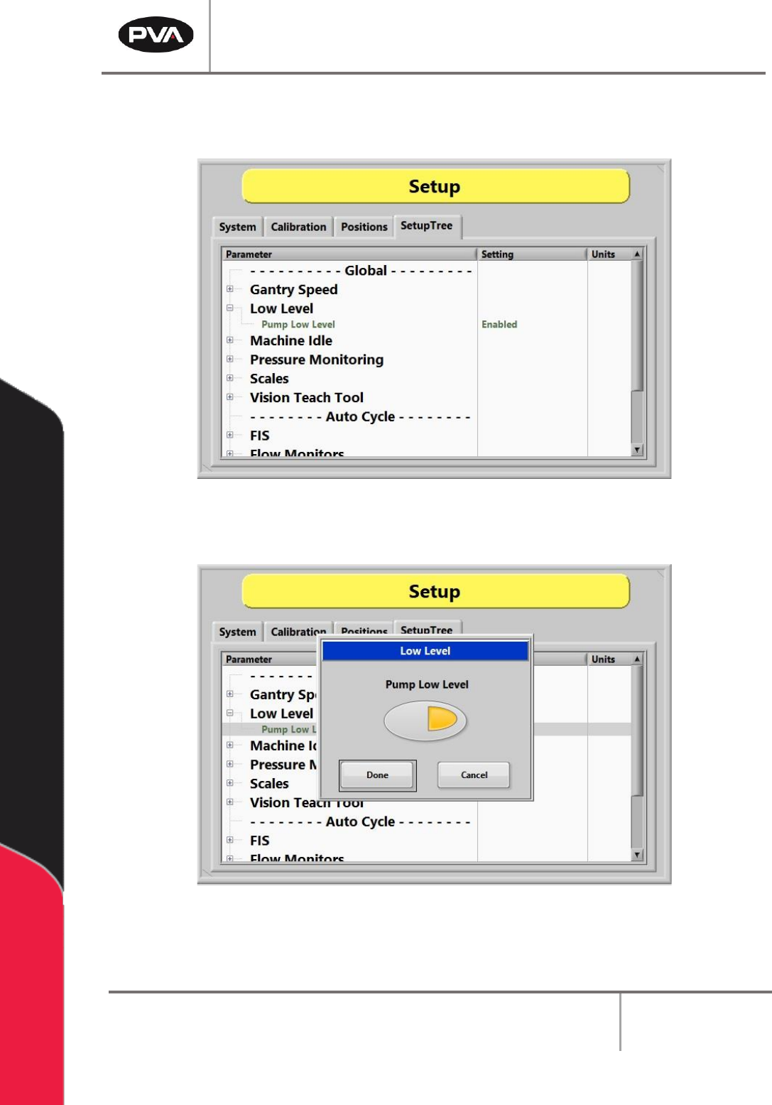
8.4.2 Low Level
Low Level sensor monitoring can be either enabled or disabled in the SetupTree tab.
Figure 42: Low Level Sensor Monitoring Enabled
Figure 43: Adjusting Low Level Sensor Monitoring
PVA Portal Manual
Revision I / January 2022
Page 47 of 106
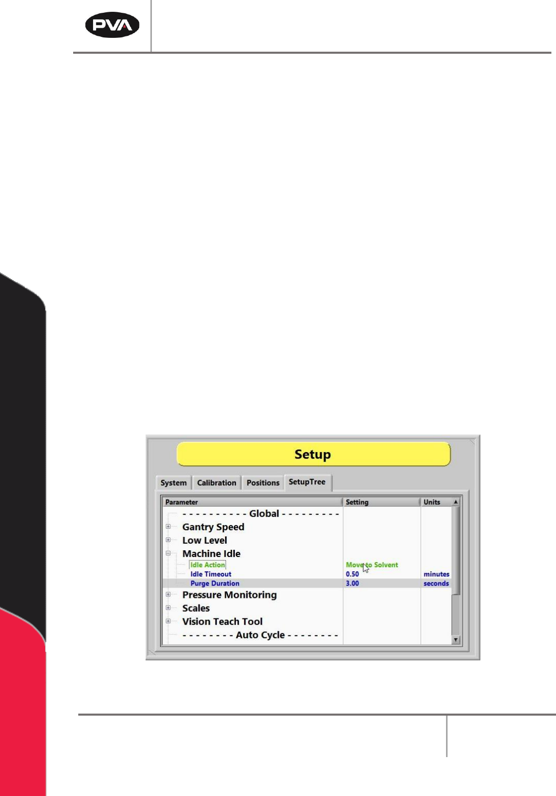
8.4.3 Machine Idle
Using the Machine Idle option, the purge and/or solvent cup features can be adjusted.
Auto purge dispenses material from all valves at specific intervals to prevent valves from
clogging. The default setting depends on the material used. The workcell only auto purges
when in Auto Cycle or Cycle Stop. The workcell does not auto purge in other modes but
will immediately auto purge when returned to the Cycle Stop or Auto Cycle modes, if
necessary.
Note: If the workcell has solvent cups, the solvent cup routine overrides the auto
purge settings. The system will only purge, when necessary, with the solvent cup
sequence.
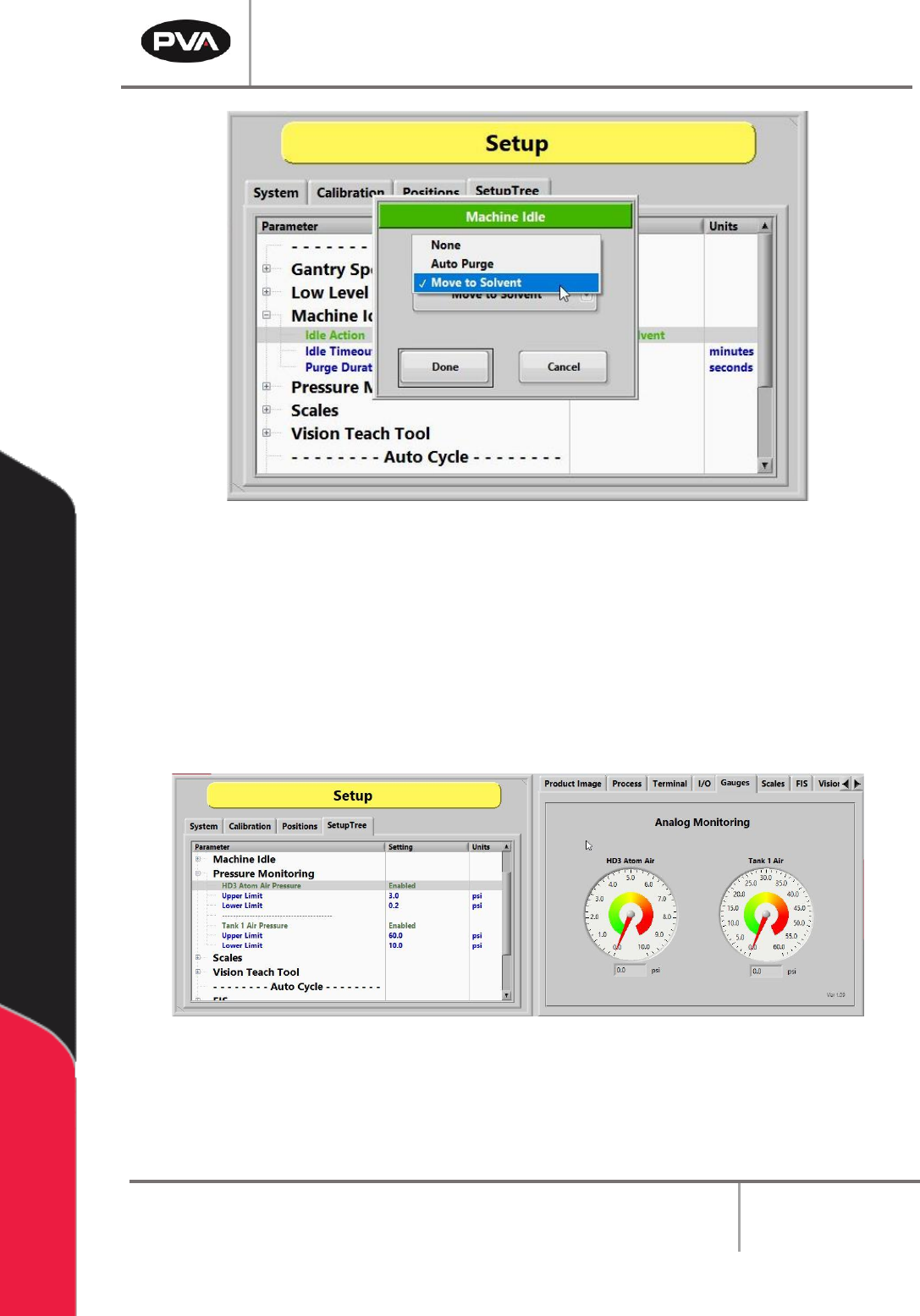
1. Select the “+” to open the "Machine Idle” drop down list.
2. Double left click on the Idle Action and select “None, Auto Purge, or Move to
Solvent” to set the function. When set to "None", the head will move to the taught
Standby Position. For more information on setting Idle Positions, refer to Section
8.3.
3. Set the Idle Timeout in minutes of how often the valves will purge or the duration
of inactivity during Auto Cycle before the heads move to the solvent cups.
4. Set the Purge Duration in seconds for the time for which the valves will purge. This
applies to both auto purge and solvent options.
Figure 44: Adjust Machine Idle Options
PVA Portal Manual
Revision I / January 2022
Page 48 of 106
Figure 45: Adjusting Machine Idle Action
8.4.4 Pressure Monitoring
Pressure Monitoring is used to verify the digital gauges installed on the system. When
enabled, the monitoring will set an alarm flag and display a message if the pressure is
outside the specified ranges for the Upper and Lower Limits.
The Upper Limit and the Lower Limit can be adjusted as needed for the process.
Figure 46: Adjust Pressure Monitoring in SetupTree Tab