Portal-Operation-Manual-REV-I.pdf - 第92页
PVA Portal Manual Revision I / Janua ry 2022 Page 92 of 106 15.3 Resettin g the Exhaust Fan Overload Rela y Machines with exhaust fans may hav e errors if the overload rela ys trip. Perform the following steps to return …
PVA Portal Manual
Revision I / January 2022
Page 91 of 106
15.2 Low Material Level
There are three common ways to monitor the material level:
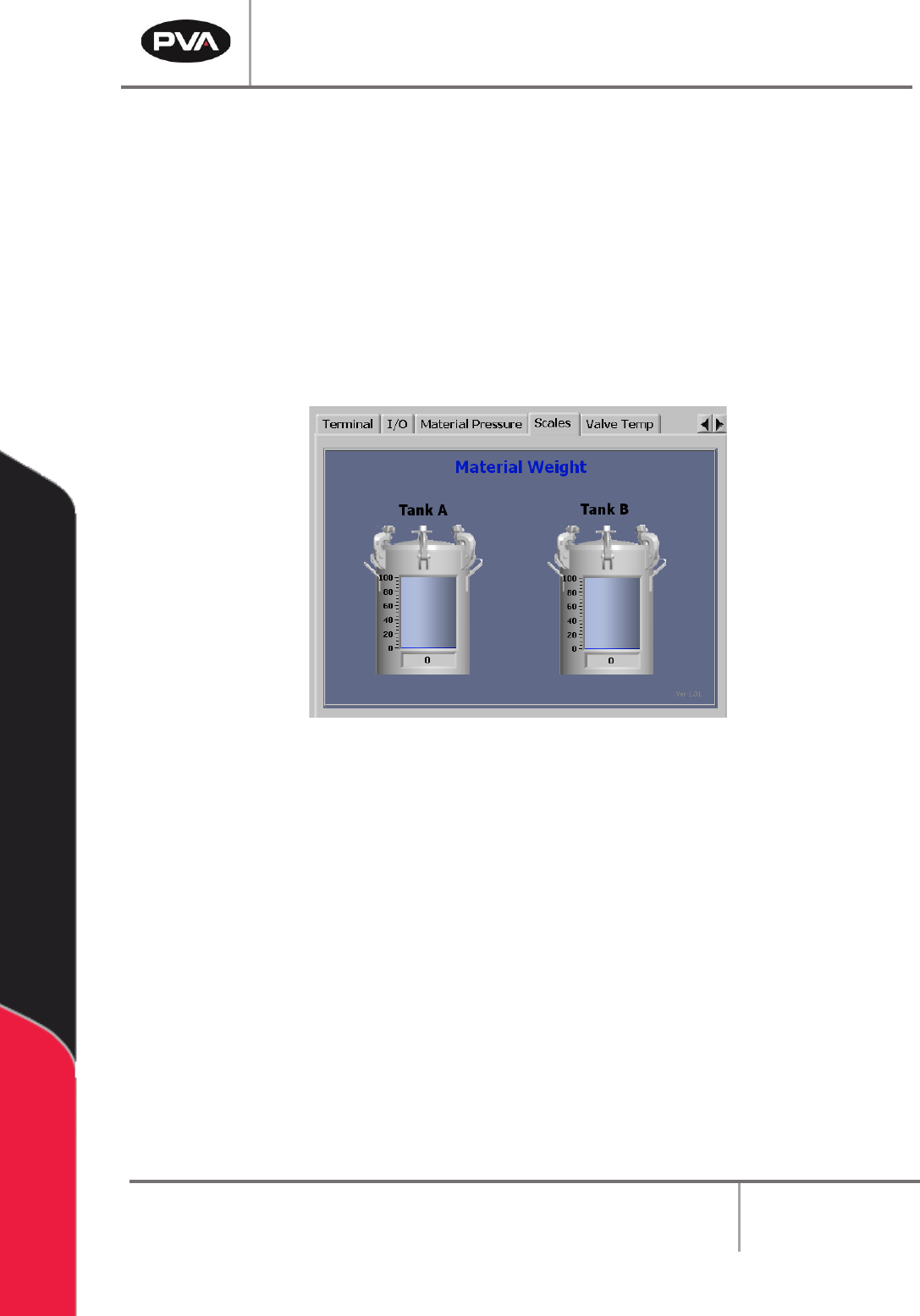
• Scales are the most common and flexible option to monitor the material level. They
have two settings: one for a low material level and one for an empty level. When the
low material level is reached, the operator will be shown a message, but the workcell
will continue to operate. When the empty level is reached, the workcell will stop
operating. To view the amount of a material in a tank, select the Scales tab on the
right side of the Portal screen. This option can be viewed in any mode. Refer to
Section 9.6 for more information on Scales.
Figure 117: Material Level in Scales Tab
• Floats are an additional way to monitor the material level. However, this option will
only notify the operator when the material is low.
• Proximity Sensors are used for cartridges or syringes. The proximity sensor is
activated when the ram moves to the low material position.
The workcell only measures the material level(s) when in Auto Cycle or Manual “One Shot
Wet” mode. If there is a material level error, the machine can operate in all modes, except
for Auto Cycle or Manual “One Shot Wet” mode, until the material level is raised above the
low level.
Note: A low material level will not stop a cycle. The cycle will complete the path
program and then stop machine operation.
PVA Portal Manual
Revision I / January 2022
Page 92 of 106
15.3 Resetting the Exhaust Fan Overload Relay
Machines with exhaust fans may have errors if the overload relays trip. Perform the
following steps to return to normal operation:
1. Set the main power switch to the “OFF” position.
2. Open the electrical enclosure and examine the overload relay for a tripped flag.
3. Confirm that the current set point is set correctly on the overload relay. Examine
the rating on the exhaust fan housing for current draw.
4. If necessary, push the “Reset” button to reset the relay.
5. Restart the machine.
6. If the problem persists, refer to the Workcell Installation Guidelines Troubleshooting
Maintenance Manual or contact PVA Customer Service for more information.
15.4 Pneumatic Error Recovery Procedure
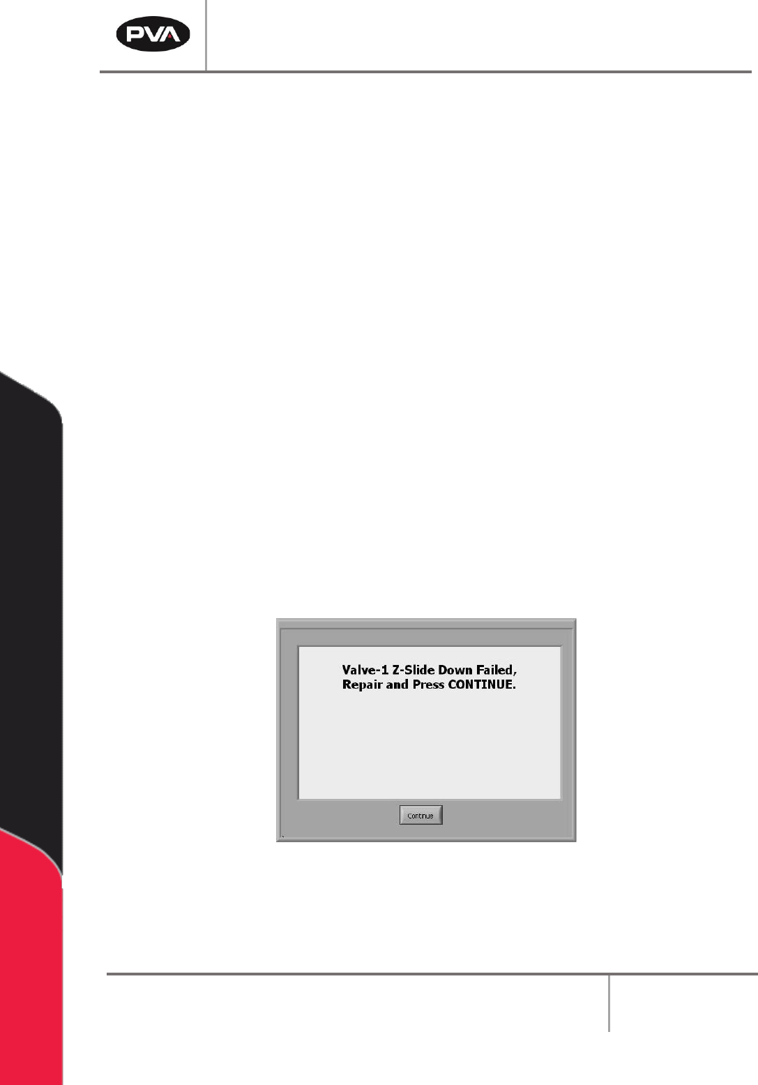
The system’s pneumatics are checked for errors every time they operate. The pneumatics
must be in their home position before the axes can home or move to the standby position.
If a pneumatic fails, an error will be shown.
Figure 118: Pneumatic Error Example
1. Find the cause of the problem.
2. Correct the problem.
PVA Portal Manual
Revision I / January 2022
Page 93 of 106
3. Select the “Continue” button.
4. Refer to the Pneumatic Actuator Failure section in the Workcell Installation
Guidelines Troubleshooting Maintenance Manual for more information.
15.5 Run-Time Error Recovery Procedure
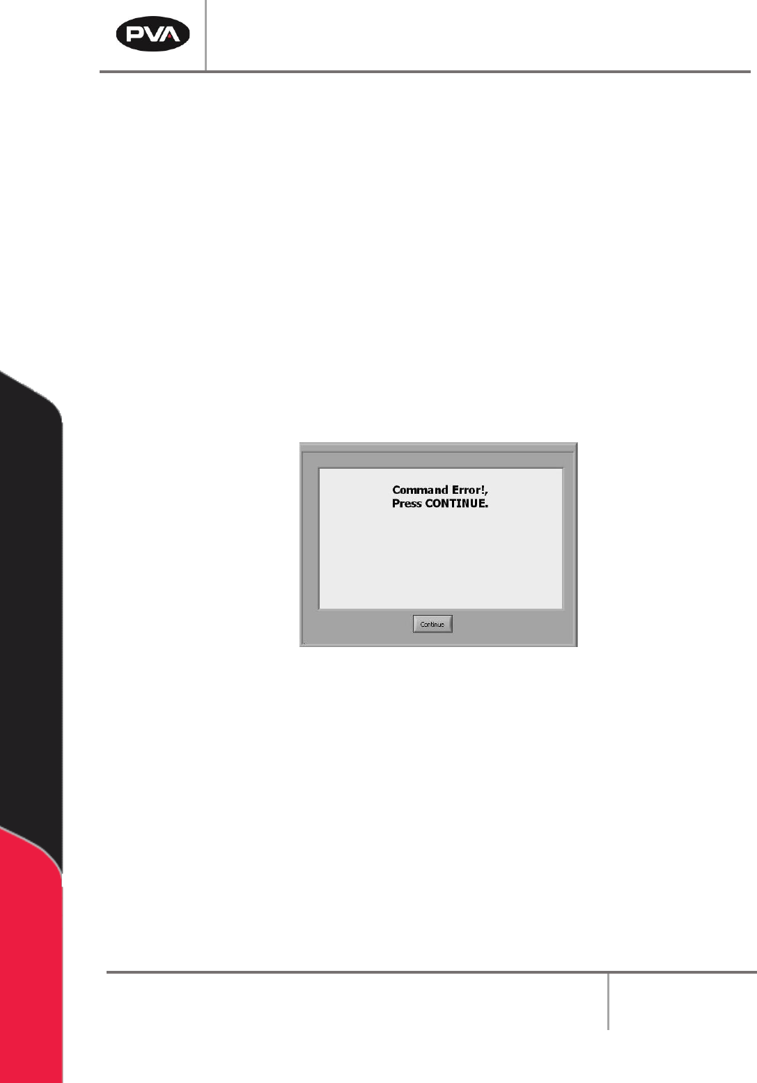
Run-time errors are generated during the operation of a program. This type of failure
should not occur during normal operation. The error type and program line number will be
displayed in the system messages window.
1. Find and record the error type, program line number, and any additional information
shown in the system messages window and contact PVA Technical Support.
2. Select the “Continue” button.
Figure 119: Command Error Example
3. Perform the Startup/Recovery Procedure. Refer to Section 15.1 for more
information.
4. Download the updated program and run it to confirm if the error was corrected.
Note: For more information on error codes, refer to the Troubleshooting guide. For
more information on programming paths, refer to the PathMaster® manual.