MD600 Series Compact AC Drive Hardware Guide-EN-B06.PDF - 第107页
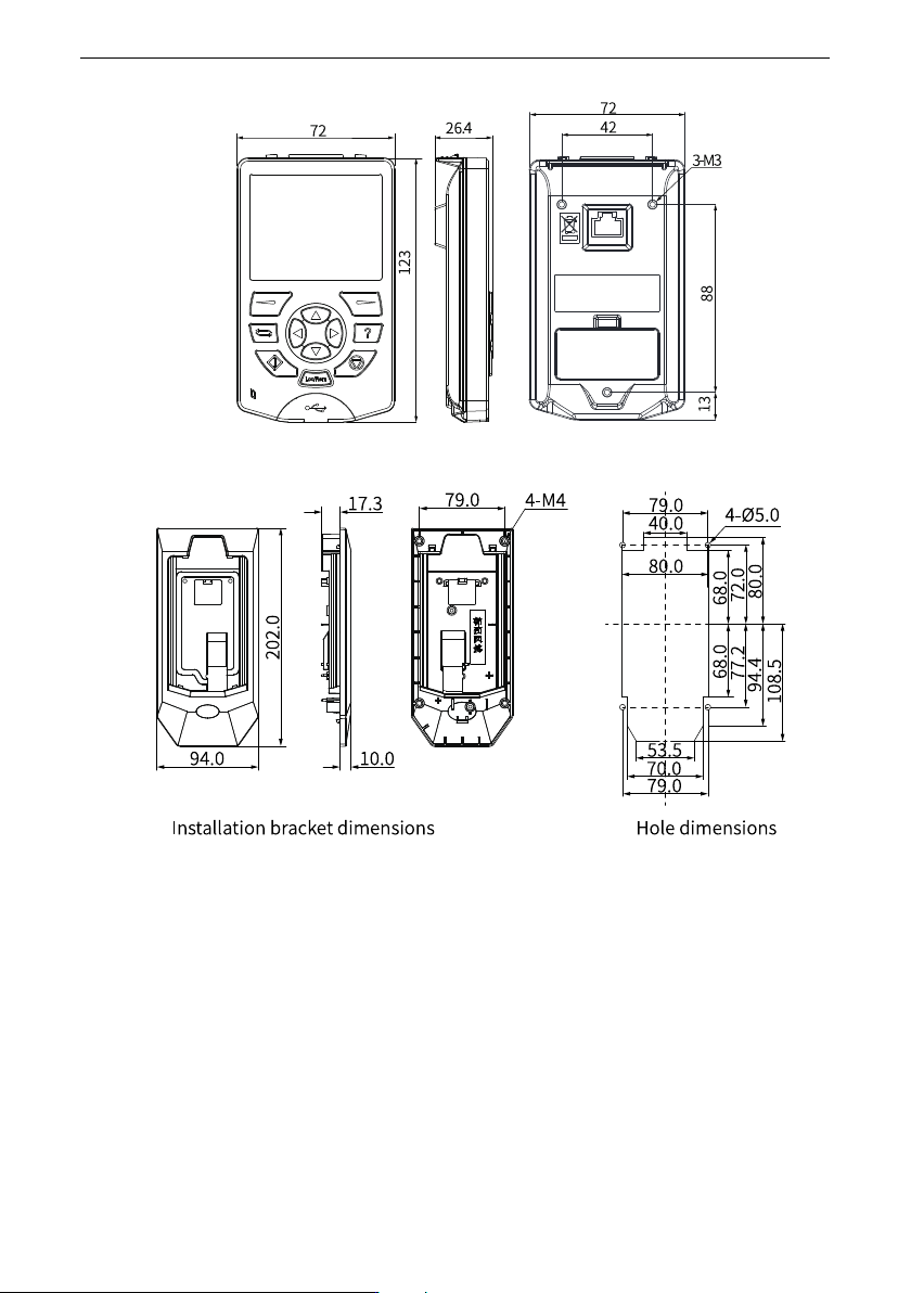
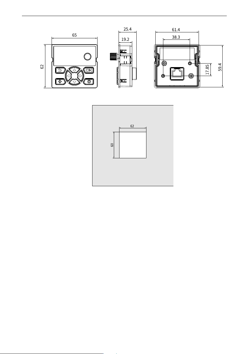
Option ‑ 106 ‑ Figure 12‑3 Dimensions (unit: mm) of the MD-BP-M Figure 12‑4 Dimensions (unit: mm) of the cabinet door opening for mounting the MD‑BP‑M through the snap‑fit joint
Option
‑107‑
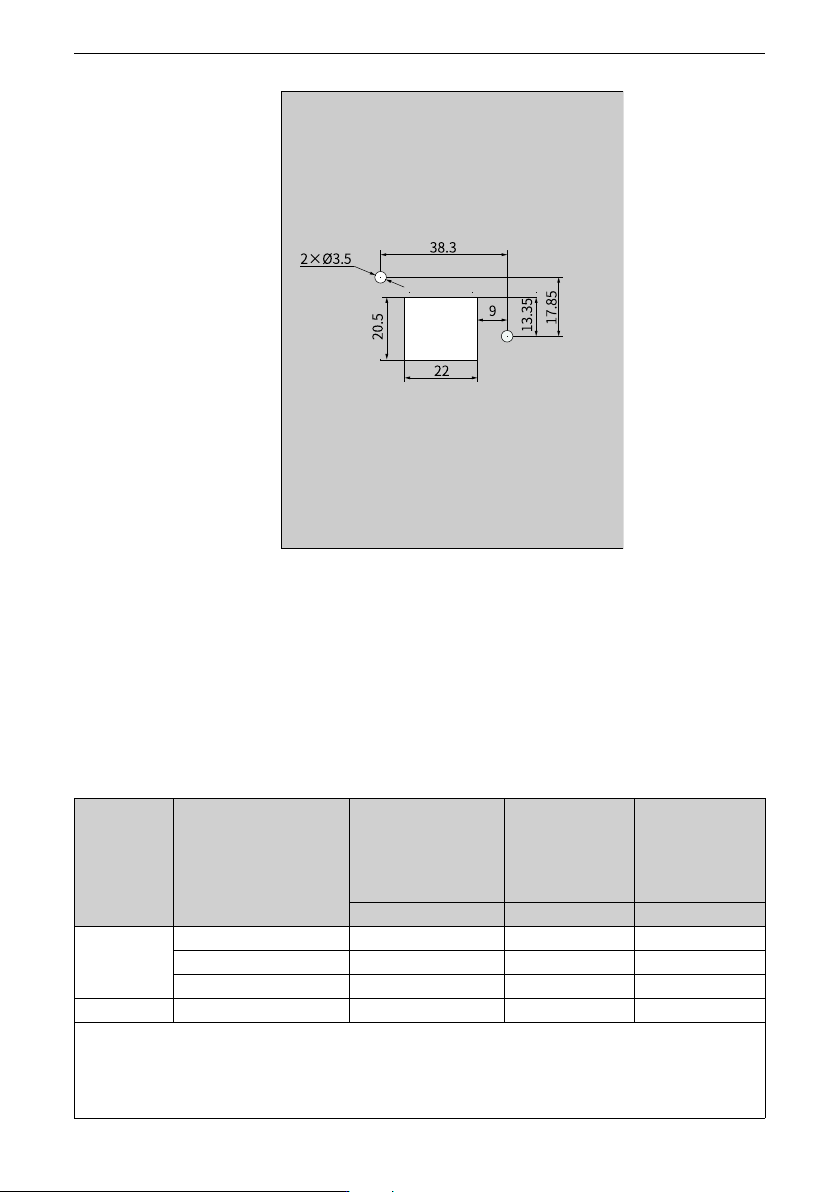
Figure 12‑5 Dimensions (unit: mm) of the cabinet door opening for mounting the MD-BP-
M with screws
12.3 Circuit Breaker and Fuse (CE)
The following tables list recommended circuit breakers, fuses, and electromagnetic
contactors.
Table 12–2 Circuit breaker, fuse, and electromagnetic contactor (single-phase 200 V to 240 V,
compliance with CE)
Structure Model
Recommended
Semiconductor Fuse
Specification
(Bussmann)
Recommended
Contactor
Specification
(Schneider)
Minimum
Specification of
Recommended D-
Type Circuit Breaker
(Schneider)
Rated current (A) Rated current (A) Rated current (A)
T1
MD600S/A–2S2R8(B)
10 9 10
MD600S/A–2S4R6(B)
15 12 16
MD600S/A–2S7R5(B)
25 18 25
T2
MD600S/A–2S010(B)
35 25 32
The recommended values in the preceding table are based on the following prerequisites:
1. The ambient temperature of the device is 40℃ and there is no forced air cooling method. The altitude is 2000 m. Only
a single drive is installed. The current-carrying density of the conductor is 1.3 A/mm².
2. If the conditions vary, select the model according to actual conditions.