MD600 Series Compact AC Drive Hardware Guide-EN-B06.PDF - 第66页
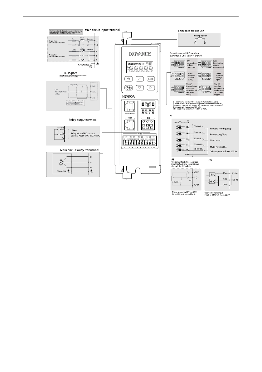
Wiring ‑65‑ Figure 6‑3 Main circuit terminal dimensions (mm) of T2 models 6.2.2 Wiring Description of Main Circuit Terminals The following rules apply to the wiring of the main circuit: ● Terminals BR, (-), and (+) are u…
Wiring
‑64‑
Terminal description
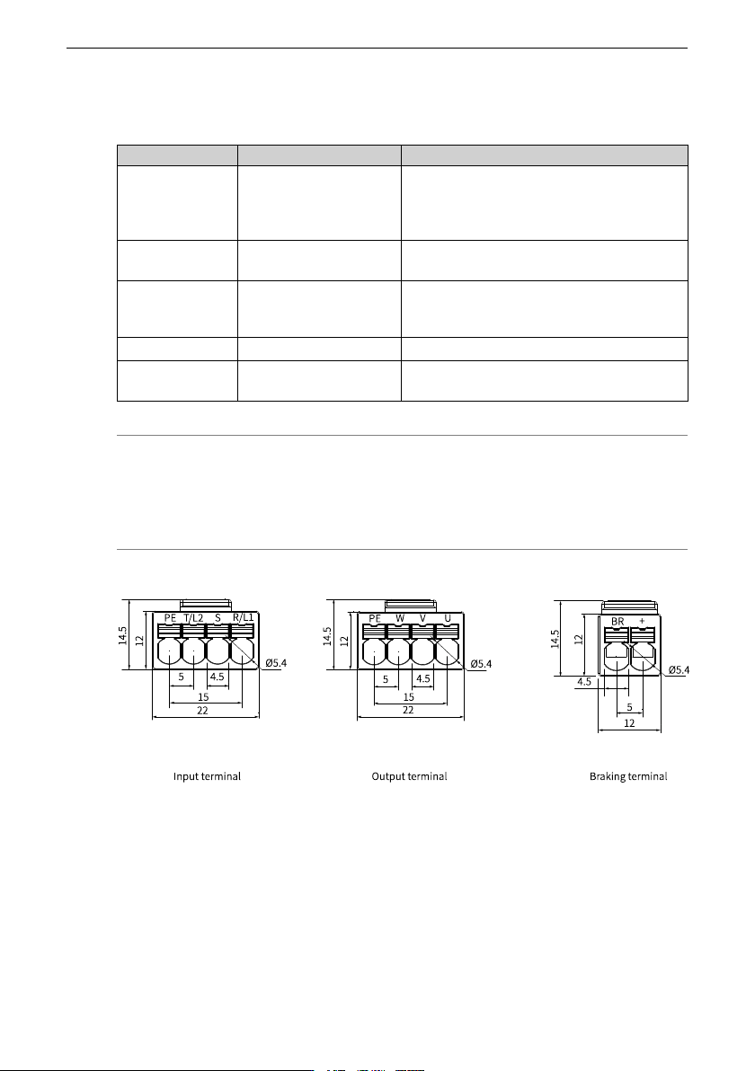
Table 6–2 Main circuit terminals of T1 to T2 models
Terminal mark Terminal
Function
L1, L2
Single-phase power
supply input terminals
The terminals are used to connect to the
power supply. L1 is connected to the live
wire and L2 is connected to the neutral
wire.
R, S, T
Three-phase power
input terminals
Connected to the three-phase AC power
supply.
(+), BR Terminals for
connecting the braking
resistor
Used to connect the braking resistor.
U, V, W
Output terminals Used to connect the three-phase motor.
PE
Grounding terminal
(PE)
Protective grounding
Note
Terminals + and BR for the braking resistor are optional and are available only on models
with the letter "B" at the end. Models without the letter "B" do not have these terminals
and do not support external braking resistors.
Terminal dimensions
Figure 6‑2 Main circuit terminal dimensions (mm) of T1 models
Wiring
‑65‑
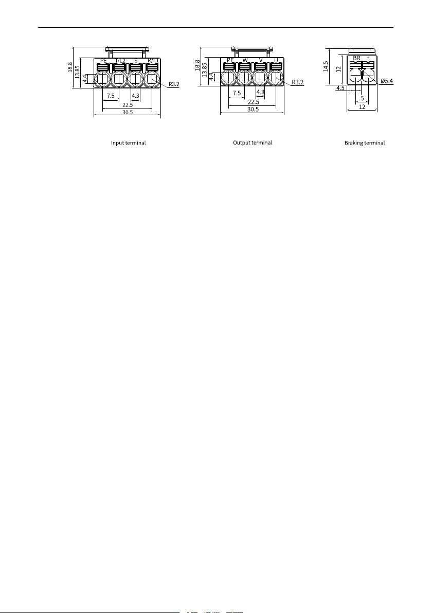
Figure 6‑3 Main circuit terminal dimensions (mm) of T2 models
6.2.2 Wiring Description of Main Circuit Terminals
The following rules apply to the wiring of the main circuit:
● Terminals BR, (-), and (+) are used to connect options. Do not connect these terminals
to an AC power supply.
● To protect the main circuit, isolate and cover it from surfaces that may come into
contact.
● The control circuit is the internal safety extra-low voltage (SELV) circuit, which must be
insulated and isolated from other circuits. Make sure that the control circuit is
connected to the external SELV circuit.
● Prevent foreign matters from entering the wiring part of the terminal block.
● Do not solder twisted conductors.
For main circuit cable specifications, see
"12.9.1 Main circuit cable
"
on page 125
.
6.2.3 Main Circuit Wiring
Context
For details on main circuit terminals and control circuit terminals, see
" Electrical De-
sign
"
on page 28
. This section describes quick control circuit wiring.
Procedure
1. Ground the AC drive.
2. Check the rated value of the circuit breaker or fuse.
3. Check whether the rated motor voltage is compatible with the AC drive voltage.
4. Connect the AC drive to the motor.
5. Connect the AC drive to the mains power.