MD600 Series Compact AC Drive Hardware Guide-EN-B06.PDF - 第35页
Electrical Design ‑ 34 ‑ Figure 4‑5 Clearance for installation of a single device Table 4–2 Clearance for installation of a single device (single-phase 200 V to 240 V) Power Rating (kW) Clearance (mm) 0.37 A1 ≥ 20 B1 ≥ 1…

Electrical Design
‑33‑
4.4 Electromagnetic Compatibility
Overview
Electromagnetic compatibility (EMC) means that a device or system can work normally in
its electromagnetic environment and the device or system does not emit electromagnetic
interference (EMI) that causes abnormal operation of other devices or systems in the
environment.
Category
Electromagnetic compatibility performance of the drive includes two aspects:
electromagnetic emission (EMI) and electromagnetic sensitivity (EMS). EMI includes
radiated emission (RE) and conducted emission (CE).
● Radiated emission (RE): interference signal radiated by the product through the port
on its housing.
● Conducted emission (CE): interference signal conducted from the product through its
cable port.
Interference and Anti-interference
Electromagnetic compatibility is a system-level concept, which indicates that the product
has certain anti-interference capabilities and does not seriously interfere with other
devices.
4.5 Cabinet Design
4.5.1 Recommended Cabinet Layout
Reserve sufficient clearance according to the power rating of the drive. The
recommended installation methods of the MD600 include single-layer installation
and multi-layer installation.
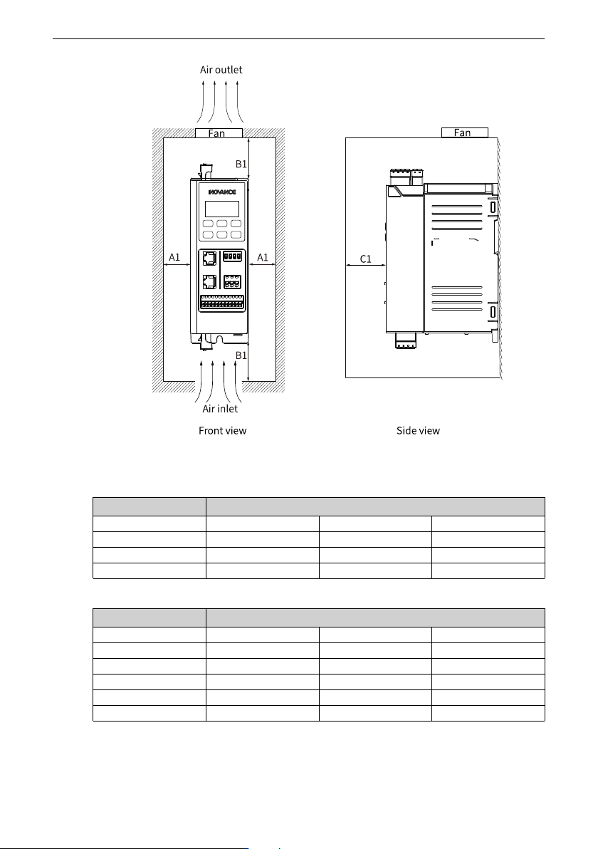
● When only a single device is installed, reserve sufficient clearance around the device,
as shown in the following figure.
Electrical Design
‑34‑
Figure 4‑5 Clearance for installation of a single device
Table 4–2 Clearance for installation of a single device (single-phase 200 V to 240 V)
Power Rating (kW) Clearance (mm)
0.37 A1 ≥ 20 B1 ≥ 100 C1 ≥ 80
0.75 A1 ≥ 20 B1 ≥ 100 C1 ≥ 80
1.5 A1 ≥ 20 B1 ≥ 100 C1 ≥ 80
2.2 A1 ≥ 20 B1 ≥ 120 C1 ≥ 80
Table 4–3 Clearance for installation of a single device (three-phase 380 V to 480 V)
Power Rating (kW) Clearance (mm)
0.37 A1 ≥ 20 B1 ≥ 100 C1 ≥ 80
0.75 A1 ≥ 20 B1 ≥ 100 C1 ≥ 80
1.5 A1 ≥ 20 B1 ≥ 100 C1 ≥ 80
2.2 A1 ≥ 20 B1 ≥ 100 C1 ≥ 80
4 A1 ≥ 20 B1 ≥ 120 C1 ≥ 80
5.5 A1 ≥ 20 B1 ≥ 120 C1 ≥ 80
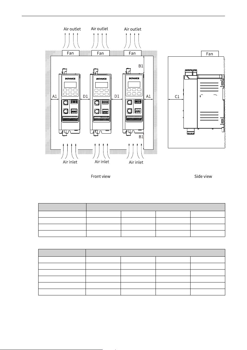
● When multiple devices are installed side by side, the minimum distance between two
devices is shown below.
Electrical Design
‑35‑
Figure 4‑6 Side-by-side installation clearance
Table 4–4 Side-by-side installation clearance (single-phase 200 V to 240 V)
Power Rating (kW) Clearance (mm)
0.37 A1 ≥ 20 B1 ≥ 100 C1 ≥ 80 D1 ≥ 30
0.75 A1 ≥ 20 B1 ≥ 100 C1 ≥ 80 D1 ≥ 0
1.5 A1 ≥ 20 B1 ≥ 100 C1 ≥ 80 D1 ≥ 0
2.2 A1 ≥ 20 B1 ≥ 120 C1 ≥ 80 D1 ≥ 0
Table 4–5 Side-by-side installation clearance (three-phase 380 V to 480 V)
Power Rating (kW) Clearance (mm)
0.37 A1 ≥ 20 B1 ≥ 100 C1 ≥ 80 D1 ≥ 30
0.75 A1 ≥ 20 B1 ≥ 100 C1 ≥ 80 D1 ≥ 30
1.5 A1 ≥ 20 B1 ≥ 100 C1 ≥ 80 D1 ≥ 0
2.2 A1 ≥ 20 B1 ≥ 100 C1 ≥ 80 D1 ≥ 0
4 A1 ≥ 20 B1 ≥ 120 C1 ≥ 80 D1 ≥ 0
5.5 A1 ≥ 20 B1 ≥ 120 C1 ≥ 80 D1 ≥ 0