MD600 Series Compact AC Drive Hardware Guide-EN-B06.PDF - 第64页
Wiring ‑63‑ 6 Wiring 6.1 Pre-wiring inspection Check the following items before wiring. Table 6–1 Pre-wiring checklist No. Item Tick 1 Cables used during wiring comply with the requirements on the cross-sectional area an…

Installation
‑62‑
Table 5–6 Post-installation checklist
No. Item
Tick
1
The ceiling height meets the minimum requirements for smooth
ventilation. The air inlet and air outlet are free of obstruction and
have sufficient space. Sufficient space is reserved for safe passing
when the cabinet door is opened.
□
2
All contact protection devices (such as the guard plate) inside and
outside the cabinet are installed.
□
Wiring
‑63‑
6 Wiring
6.1 Pre-wiring inspection
Check the following items before wiring.
Table 6–1 Pre-wiring checklist
No. Item
Tick
1
Cables used during wiring comply with the requirements on the
cross-sectional area and the shield.
□
2
The equipment and the drive are grounded properly.
□
3
Take proper electrostatic discharge (ESD) measures and wear an
antistatic wrist strap.
□
6.2 Main Circuit Connection
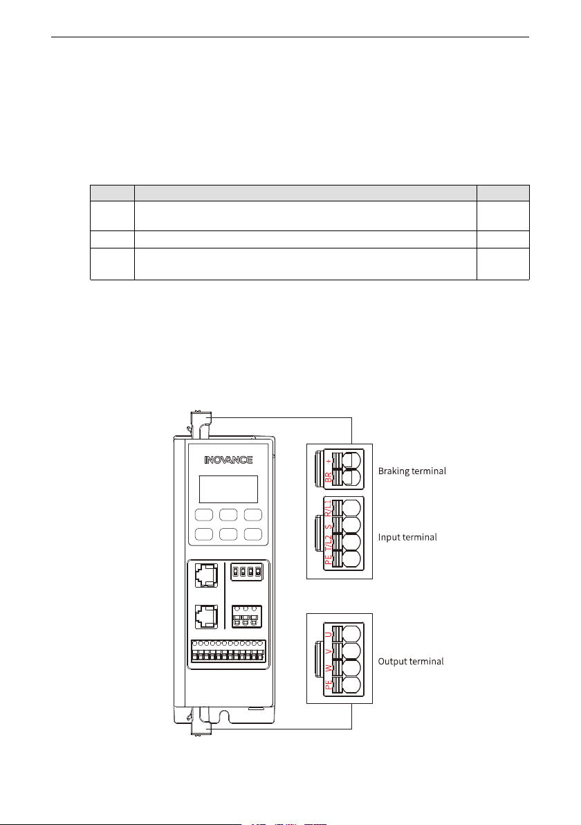
6.2.1 Descriptions of Main Circuit Terminals
Terminal Layout
Figure 6‑1 Arrangement of main circuit terminals of T1 to T2 models
Wiring
‑64‑
Terminal description
Table 6–2 Main circuit terminals of T1 to T2 models
Terminal mark Terminal
Function
L1, L2
Single-phase power
supply input terminals
The terminals are used to connect to the
power supply. L1 is connected to the live
wire and L2 is connected to the neutral
wire.
R, S, T
Three-phase power
input terminals
Connected to the three-phase AC power
supply.
(+), BR Terminals for
connecting the braking
resistor
Used to connect the braking resistor.
U, V, W
Output terminals Used to connect the three-phase motor.
PE
Grounding terminal
(PE)
Protective grounding
Note
Terminals + and BR for the braking resistor are optional and are available only on models
with the letter "B" at the end. Models without the letter "B" do not have these terminals
and do not support external braking resistors.
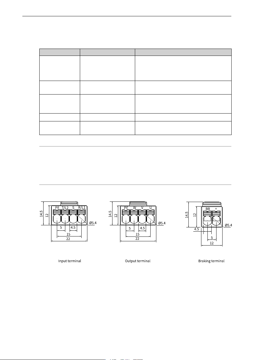
Terminal dimensions
Figure 6‑2 Main circuit terminal dimensions (mm) of T1 models