MD600 Series Compact AC Drive Hardware Guide-EN-B06.PDF - 第37页
Electrical Design ‑ 36 ‑ Note ● Three-phase 0.37 kW to 0.75 kW models and single-phase 0.37 kW models are naturally ventilated, whereas the rest models are air-cooled. ● For the naturally-ventilated models, if they are i…
Electrical Design
‑35‑
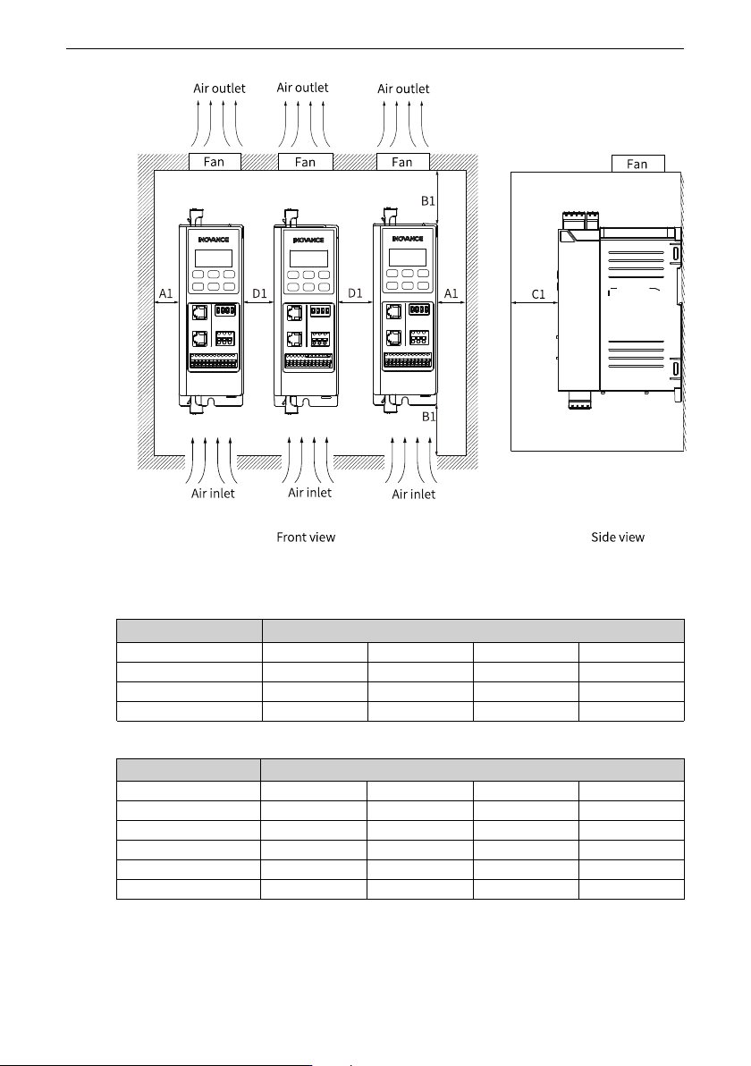
Figure 4‑6 Side-by-side installation clearance
Table 4–4 Side-by-side installation clearance (single-phase 200 V to 240 V)
Power Rating (kW) Clearance (mm)
0.37 A1 ≥ 20 B1 ≥ 100 C1 ≥ 80 D1 ≥ 30
0.75 A1 ≥ 20 B1 ≥ 100 C1 ≥ 80 D1 ≥ 0
1.5 A1 ≥ 20 B1 ≥ 100 C1 ≥ 80 D1 ≥ 0
2.2 A1 ≥ 20 B1 ≥ 120 C1 ≥ 80 D1 ≥ 0
Table 4–5 Side-by-side installation clearance (three-phase 380 V to 480 V)
Power Rating (kW) Clearance (mm)
0.37 A1 ≥ 20 B1 ≥ 100 C1 ≥ 80 D1 ≥ 30
0.75 A1 ≥ 20 B1 ≥ 100 C1 ≥ 80 D1 ≥ 30
1.5 A1 ≥ 20 B1 ≥ 100 C1 ≥ 80 D1 ≥ 0
2.2 A1 ≥ 20 B1 ≥ 100 C1 ≥ 80 D1 ≥ 0
4 A1 ≥ 20 B1 ≥ 120 C1 ≥ 80 D1 ≥ 0
5.5 A1 ≥ 20 B1 ≥ 120 C1 ≥ 80 D1 ≥ 0

Electrical Design
‑36‑
Note
● Three-phase 0.37 kW to 0.75 kW models and single-phase 0.37 kW models are
naturally ventilated, whereas the rest models are air-cooled.
● For the naturally-ventilated models, if they are installed side-by-side, a distance
of at least 30 mm must be reserved between two adjacent models.
● The air-cooled model supports side-by-side mounting without any space
between two models.
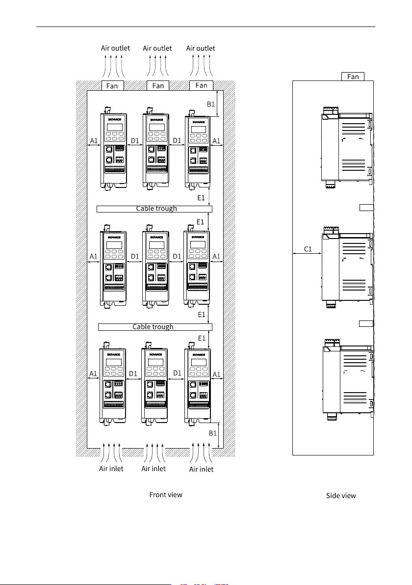
● When devices are installed at different layers, the minimum distance between two
layers is shown below.