MD600 Series Compact AC Drive Hardware Guide-EN-B06.PDF - 第79页
Wiring ‑ 78 ‑ 6.4 Communication Wiring 6.4.1 RS485 Communication Wiring Use a three-conductor shielded cable as the RS485 bus to connect to 485+, 485-, and GND terminals of the AC drive. Use the twisted pair cable to con…
Wiring
‑77‑
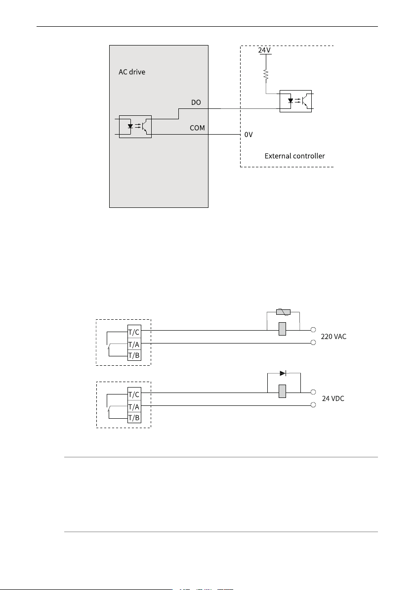
Figure 6‑13 DO connecting to external controller
Wiring of Relay Output Terminals
The inductive load (relay, contactor, and motor) causes voltage peak after the current is
removed. To minimize the interference at cutoff, connect a voltage dependent resistor to
the relay contact and connect absorption circuits, such as voltage dependent resistors,
RC absorption circuits, and diodes, to other inductive loads, as shown in
"Figure 6–14
Anti-interference treatment for relay output terminals
"
on page 77
.
Figure 6‑14 Anti-interference treatment for relay output terminals
Note
● The power supply connected with the control circuit must use class 2 power
supply; otherwise, the operation performance of the AC drive will be degraded.
● For control cable specifications, see "Control Circuit Cable" in MD600 Series
Compact AC Drive User Guide.
Wiring
‑78‑
6.4 Communication Wiring
6.4.1 RS485 Communication Wiring
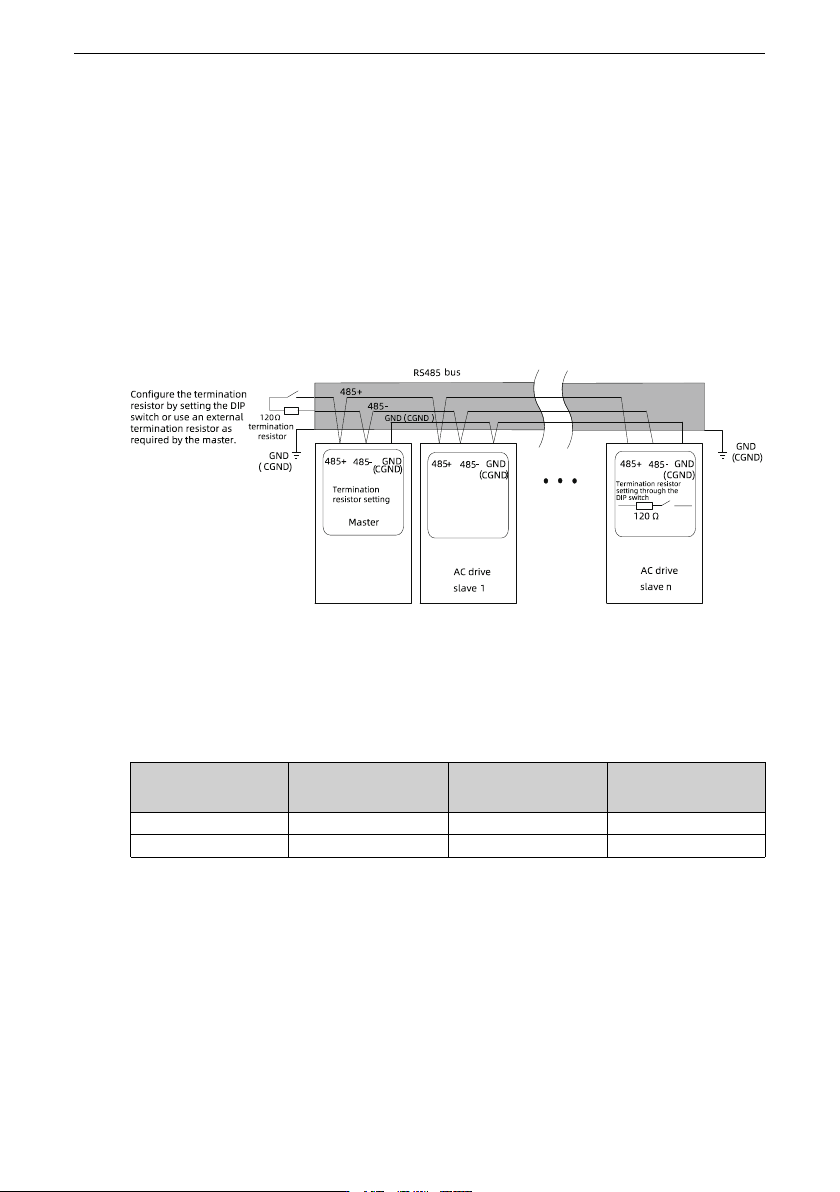
Use a three-conductor shielded cable as the RS485 bus to connect to 485+, 485-, and
GND terminals of the AC drive. Use the twisted pair cable to connect to the 485+ and 485-
terminals and use the other cable to connect to the RS485 reference ground terminal
GND. Connect the shield to the equipment ground. In the following figure, the left
termination resistor is set by the DIP switch on the master. If the master does not have a
built-in termination resistor, install an external termination resistor. The right termination
resistor is also set by the DIP switch.
Figure 6‑15 RS485 bus topology
The maximum number of nodes and transmission distance of a standard RS485 circuit
vary with the transmission rate, as listed in the following table.
Table 6–5 Transmission distance and number of nodes
Transmission
distance (m)
Transmission Rate
(kbps)
Number of Nodes Cross-Sectional
Area
100 115.2 128 26 AWG
1000 19.2 128 26 AWG
6.4.2 CAN Wiring
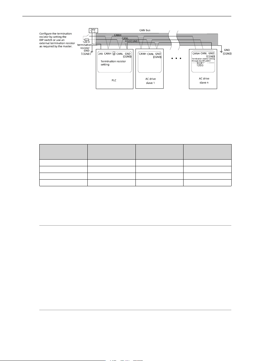
Use the daisy chain mode for the CAN bus, as shown in the following figure. Use shielded
twisted pair cables for the CAN bus, and use twisted pair cables for CANH and CANL
signal cables. In the following figure, the left termination resistor is set by the DIP switch
or an external termination resistor is installed. The right termination resistor is also set by
the DIP switch. Connect the reference grounds for CAN signals of all the nodes (up to 64
nodes) together.
Wiring
‑79‑
Figure 6‑16 CAN bus topology
The transmission distance of the CAN bus is directly related to the baud rate and the
communication cable. The following table describes the relationship between the
maximum bus length and the baud rate.
Table 6–6 Transmission distance and baud rate
Transmission
distance (m)
Transmission Rate
(kbps)
Number of Nodes Cross Sectional Area
(mm
2
)
25 1000 64 0.205
95 500 64 0.34
560 100 64 0.5
1100 50 64 0.75
6.5 Grounding requirements
To properly ground the servo drive, observe the following requirements:
Note
● To prevent electric shock, ground the grounding terminal properly. Observe
related national or regional regulations during grounding.
● To prevent electric shocks, ensure that the protective grounding conductor
meets the technical specifications and local safety standards, and shorten the
grounding cable length as much as possible.
● The leakage current of a single drive does not exceed 3.5 mA AC or 10 mA DC.
You only need to configure one protective grounding conductor with the same
specifications as the phase cable.
● When using multiple devices, follow the instructions for grounding all devices.
Incorrect grounding can result in misoperation of devices.