MD600 Series Compact AC Drive Hardware Guide-EN-B06.PDF - 第27页
System Connection ‑ 26 ‑ 3 System Connection When using the AC drive to drive an asynchronous motor, a variety of electrical components must be installed on both input and output sides to ensure system safety and stabili…
Product Information
‑25‑
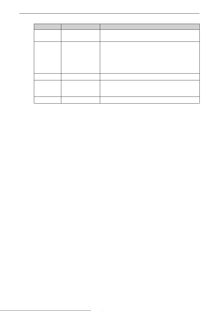
No. Name
Remarks
7
Relay terminal
(CN3)
Relay output terminal
8
R (L1)/S/T (L2)/PE
input terminals
It is used to connect three-phase/single-phase AC
input power supplies. R/S/T terminals are used to
connect the three-phase power supply. L1/L2
terminals are used to connect the single-phase
power supply, and PE is the protective earthing
terminal.
9
Braking terminal It is used to connect the braking resistor.
10
U/V/W/PE output
terminals
U/V/W terminals are used to connect the three-
phase motor, and PE is the protective earthing
terminal.
11
Cooling fan It is used for heat dissipation.
System Connection
‑26‑
3 System Connection
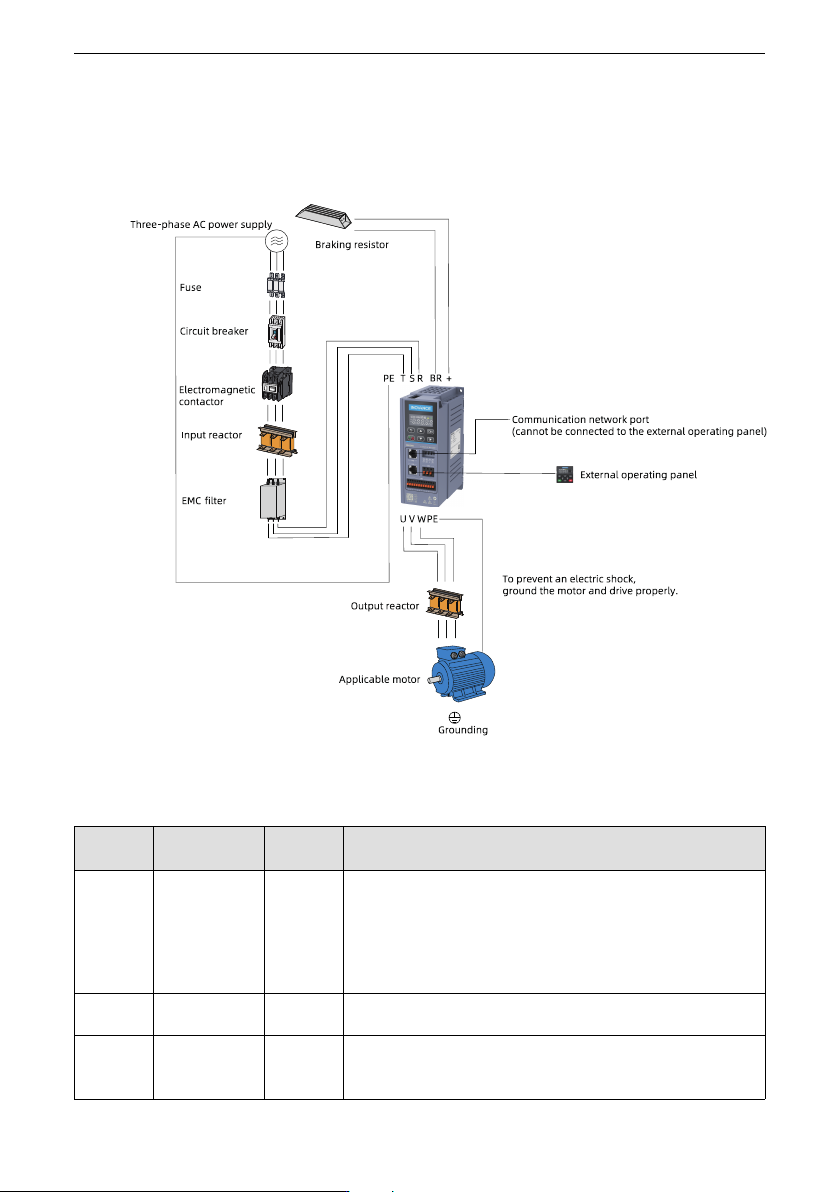
When using the AC drive to drive an asynchronous motor, a variety of electrical
components must be installed on both input and output sides to ensure system safety
and stability. The following figure shows the system composition.
Figure 3‑1 System Connection
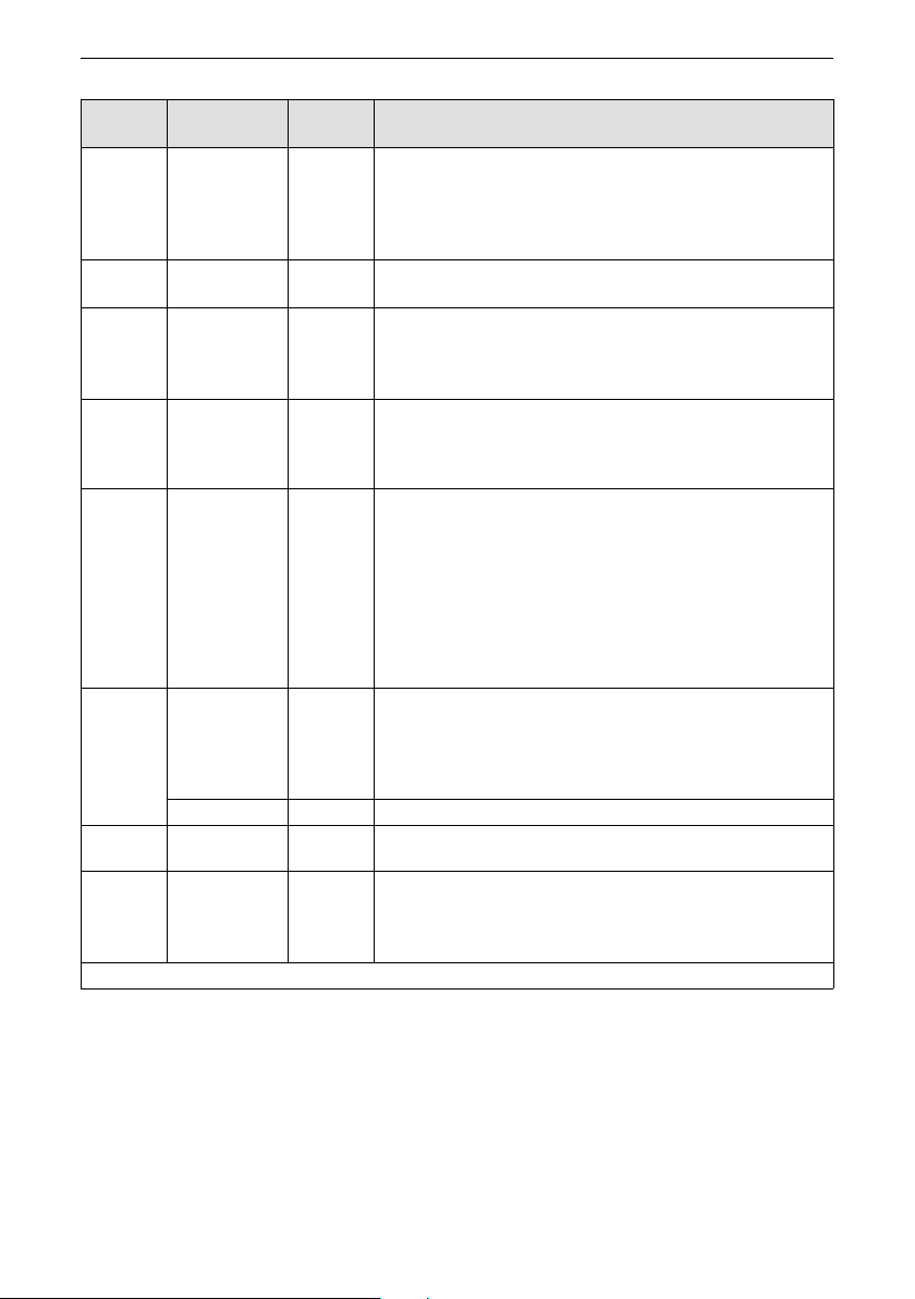
Table 3–1 Description of electrical peripherals
Component
Installation
position
Applicable
model
Function overview
Circuit
breaker
Input side of the
drive
All models Installed between the power supply and input side of the drive.
Short circuit breaker: Cuts off the power supply when overcurrent occurs
on downstream devices to prevent accidents.
Residual current device (RCD): The drive may generate high-frequency
leakage current during running. To prevent electric shock which may
cause a fire, select a proper RCD based on actual applications.
Fuse Input side of the
drive
All models Provides protection in case of short circuit to protect downstream
semiconductors.
Electromag
netic
contactor
Input side of the
drive
All models It is used to connect to or cut off the power supply of the AC drive. Do
not use the contactor to power on or off the drive frequently (interval: at
least one hour) or use the contactor to directly start the drive.
System Connection
‑27‑
Component
Installation
position
Applicable
model
Function overview
AC input
reactor
Input side of the
drive
All models It provides the following functions: Improves the power factor on the
input side.
Eliminates harmonics on the input side and prevents other devices from
being damaged due to voltage waveform distortion.
Eliminates input current unbalance caused by inter-phase unbalance.
EMC filter Input side of the
drive
All models It provides the following functions: Reduces the conduction and
radiation interference generated by the AC drive to external devices.
Simple
Filter
Input side of the
drive
All models It provides the following functions: Reduces the conduction and
radiation interference generated by the AC drive to external devices.
Decreases conduction interference flowing from the power supply to the
AC drive and improves the anti-interference capacity of the AC drive.
Braking
Resistor
Input side of the
drive
All models A drive with the model name containing letter B is equipped with a
built-in braking unit. After the braking resistor is connected to the
braking unit, the braking resistor consumes regenerative energy during
motor deceleration.
Output
reactor
Output side of
the drive
All models Harmonics are present in the output side of the drive. When motor is far
from AC drive, there is excessive distributed capacitance in the circuit.
Certain harmonics may cause resonance in the circuit, which can:
● Degrade the motor insulation performance and damages the motor in
the long time.
● Generates large leakage current and causes frequent AC drive
protection trips.
The output reactor can protect motor insulation and reduce bearing
current, prolonging the service life of the motor.
Magnetic
ring and
magnetic
buckle
AC drive input
side or output
side
All models When installed on the input side, the ferrite ring can be used to suppress
the noise in the input power supply system of the drive. When installed
on the output side, the ferrite ring can be used to suppress interference
generated by the drive to external devices and reduce the bearing
current.
Signal cable All models Improves the anti-interference performance of signals.
Motor Output side of
the drive
All models Select an applicable motor.
External
operating
panel
Connect the
external
operating panel
to the CN2 port.
All models LCD operating panel SOP-20-810 and LED operating panel MD-BP-M.
Note: For selection of peripheral electrical devices, see
" Accessory Specifications
"
on page 103
.