MD600 Series Compact AC Drive Hardware Guide-EN-B06.PDF - 第50页
Electrical Design ‑49‑ Figure 4‑16 Laying multiple types of cables ● Requirements on handing of shielded cables Minimize the length of the unshielded part of a shielded cable, and connect the shield to the nearest PE ter…
Electrical Design
‑48‑
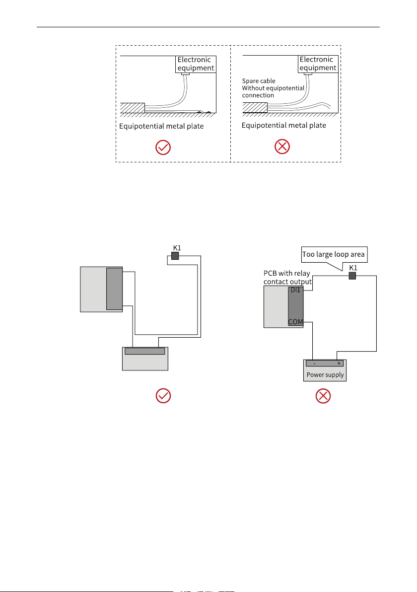
Figure 4‑14 Handling of unused conductors in a multi-conductor cable
● Requirements on the wiring loop area
For cables that transmit low-level sensor signals and shared cables that transmit
relay signals, lay them close to each other to avoid a large loop area. Use twisted pair
cables for analog signals. Lay digital signal cables close to each other.
Figure 4‑15 Recommended wiring loop area
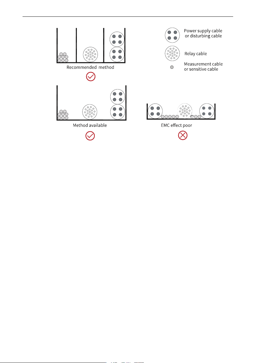
● Laying multiple types of cables
For cables of different types, route the cables along the equipotential metal plate. To
enhance the internal EMC performance, separate different types of cables or separate
cables with metal separators (recommended) in the same metal (zinc‑iron or stainless
steel) duct, as shown below.
Electrical Design
‑49‑
Figure 4‑16 Laying multiple types of cables
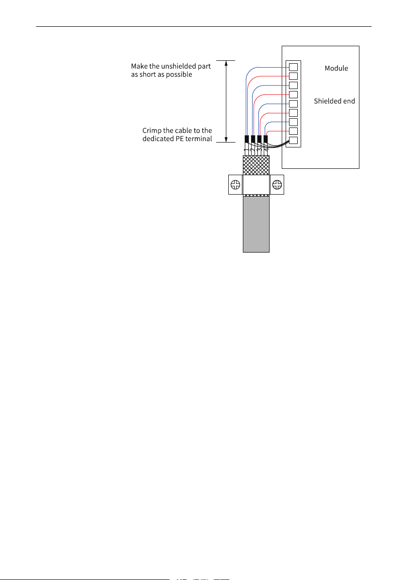
● Requirements on handing of shielded cables
Minimize the length of the unshielded part of a shielded cable, and connect the shield
to the nearest PE terminal. If the unshielded part is too long, the cable conductor is
prone to signal interference. There is no dedicated PE terminal on the drive enclosure.
In this case, connect the shield to an external PE terminal, as shown below.
Electrical Design
‑50‑
Figure 4‑17 Requirements on shielded cable
4.6 Solutions to Common EMC Issues
4.6.1 Harmonic Suppression Measures
To suppress the high harmonic current of this product and improve the power factor,
install an AC input reactor on the input side of the product. This will enable the product to
meet standard requirements.
4.6.2 Residual Current Device Misoperation
When malfunction occurs on the residual current device (RCD), take the following
measures.