MD600 Series Compact AC Drive Hardware Guide-EN-B06.PDF - 第70页
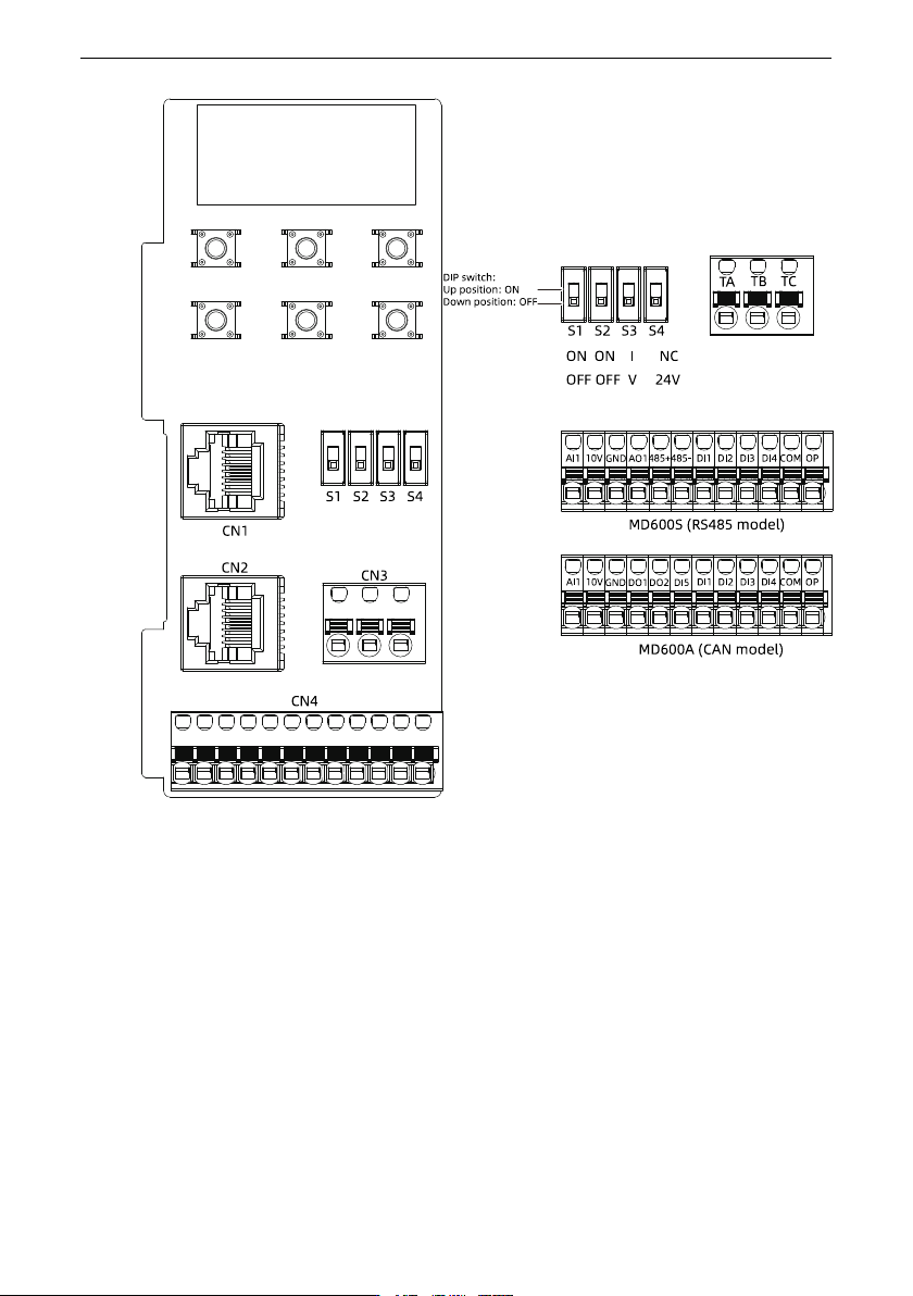
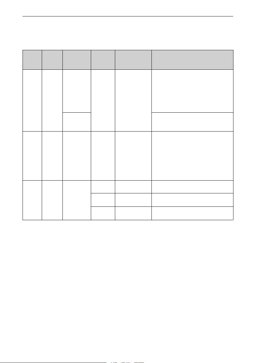
Wiring ‑69‑ Terminal description Table 6–3 Descriptions of Control Circuit Terminals External terminal Terminal type Transmission information type Terminal mark Terminal name Function CN1 RJ45 Modbus communica tion - Com…
Wiring
‑69‑
Terminal description
Table 6–3 Descriptions of Control Circuit Terminals
External
terminal
Terminal
type
Transmission
information
type
Terminal
mark
Terminal name Function
CN1
RJ45
Modbus
communica
tion
-
Communication
port
The CN1 interface of the MD600S and
MD600A models supports connection with
the commissioning software through
Modbus RTU, but does not support
connection with the operating panel.
The CN1 interface supports communication
with the PLC.
CAN
communica
tion
The CN1 terminal of the MD600A models
supports CANopen/CANlink communication.
CN2 RJ45 Modbus
communica
tion
CAN
communica
tion
- Communication
port
External operating
panel port
The CN2 terminal of the MD600S and MD600A
models supports connection with the
operating panel through the Modbus RTU
and supports connection with the operating
panel.
The CN2 interface of the MD600A models
also supports CANopen/CANlink
communication.
CN3 3-pin
terminal
block
Digital output TA Relay output Common terminal T/A of external relay
contact
TB Relay output Normally closed (NC) terminal T/B of
external relay contact
TC Relay output Normally open (NO) terminal T/C of external
relay contact
Wiring
‑70‑
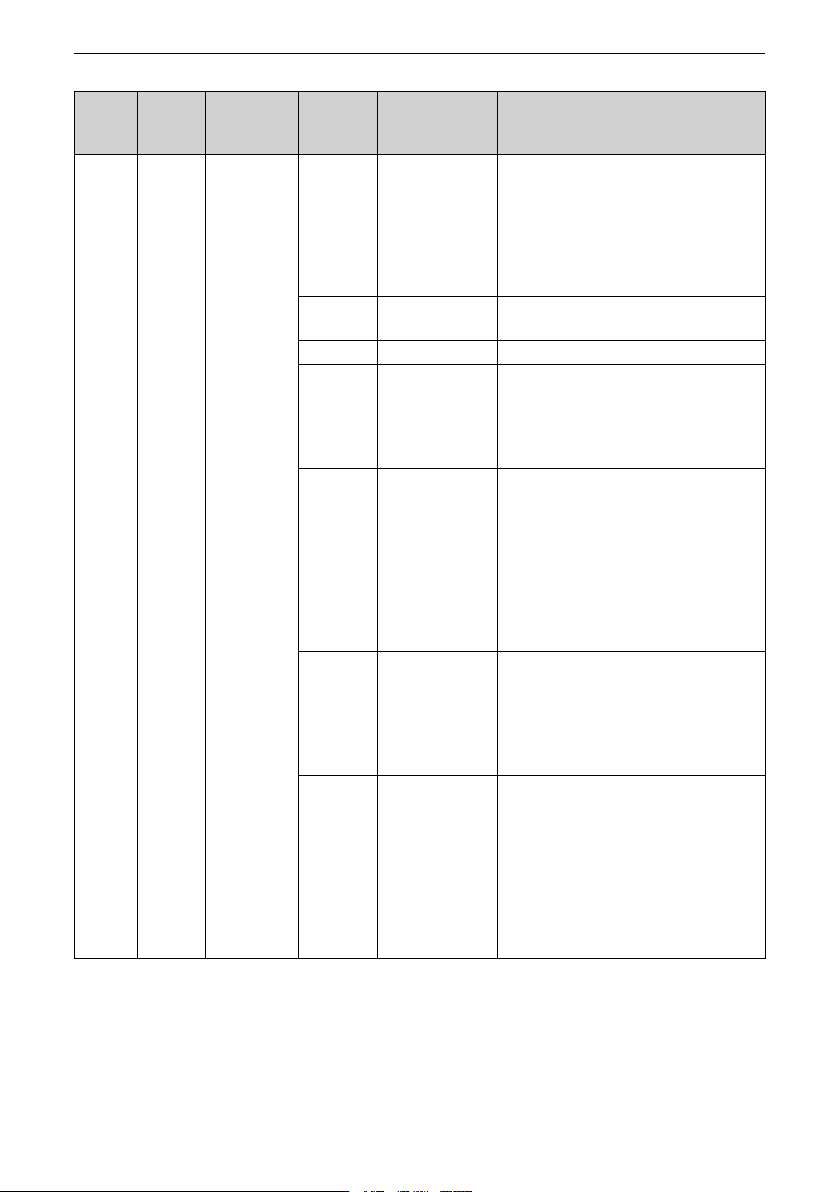
External
terminal
Terminal
type
Transmission
information
type
Terminal
mark
Terminal name Function
CN4 12-pin
terminal
block
DI/DO/AI/AO/
RS485
AI1 Analog input
terminal 1
Voltage input of -10 V to +10 V or current
input of 0 mA to 20 mA; 12-bit resolution;
accuracy after correction: 0.3%; response
time: < 2 ms
Input impedance in the voltage input mode:
22 kΩ; input impedance in the current mode:
500 Ω
10V 10 V analog
voltage output
Output voltage range: 10 V ± 5%
Maximum output current: 10 mA
GND Analog ground Internally isolated from COM
AO1 Analog output
terminal 1
(RS485 model)
Voltage output of 0 V to 10 V; 12-bit
resolution; correction accuracy: 0.5%;
maximum load output current in the voltage
output mode: 2 mA; load impedance in the
voltage output mode: 5 kΩ
DO1 Digital output
terminal 1
(CAN model)
Photocoupler isolation; unipolar open
collector output; maximum output
frequency: 100 Hz
It cannot be connected directly to the power
supply. The pull-up resistor with the
resistance set according to the load must be
added.
Output voltage range: 0 V to 24 V
Output current range: 0 mA to 50 mA
485+ RS485
communication
signal +
(RS485 model)
Positive RS485 communication signal;
maximum speed supported by hardware:
115.2 kbps;
Transmission distance: The maximum
transmission distance corresponding to the
baud rate of 9.6 kbps is 1 km.
DO2 DO2
(CAN model)
Photocoupler isolation; unipolar open
collector output; maximum output
frequency: 100 Hz
It cannot be connected directly to the power
supply. The pull-up resistor with the
resistance set according to the load must be
added.
Output voltage range: 0 V to 24 V
Output current range: 0 mA to 50 mA