MD600 Series Compact AC Drive Hardware Guide-EN-B06.PDF - 第77页
Wiring ‑ 76 ‑ Figure 6‑12 Wiring between DO and relay Connect the snubber diode with the polarity placed correctly. Otherwise, the DO circuit will be damaged upon the DO output. DO: Optocoupler isolation; unipolarity ope…
Wiring
‑75‑
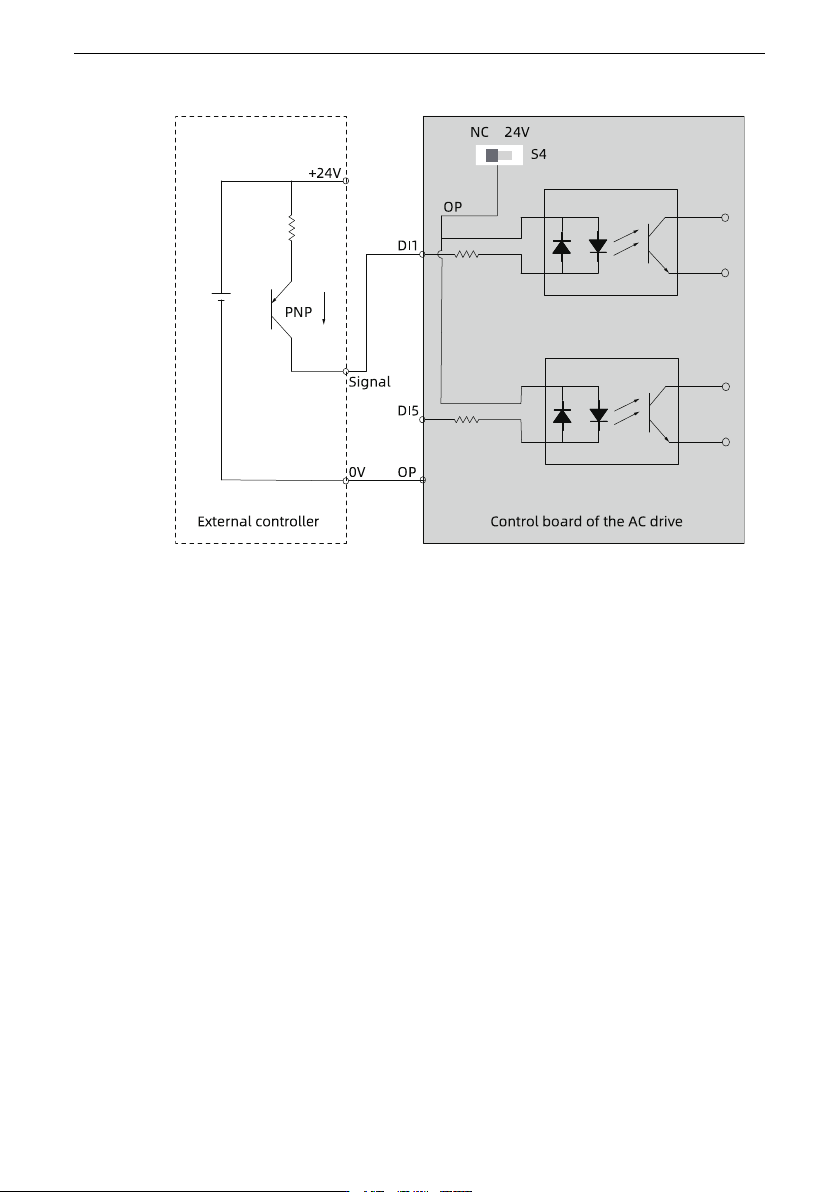
● Source wiring
Figure 6‑11 Source wiring
In the source wiring mode, you can only use the external 24 V power supply. To use
the external power supply, set the DIP switch S4 to NC (OP unconnected), connect the
OP terminal of the AC drive to the 0V terminal of the external controller, and connect
the anode of the 24 V external power supply to the DI through the control contact on
the external controller.
DO wiring
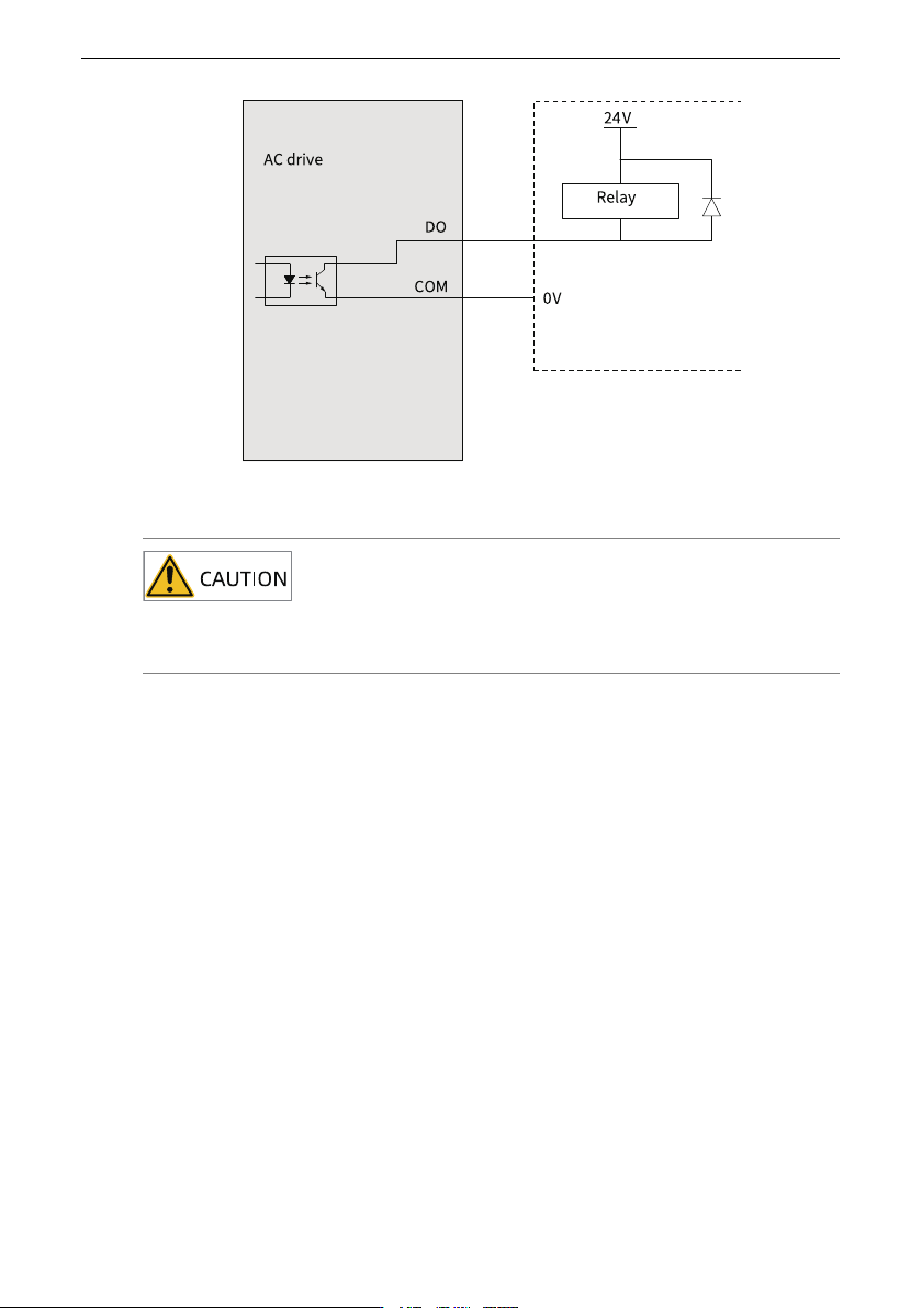
To use the DO terminal to drive a relay, connect a snubber diode to both ends of the relay
coil. Otherwise, it may cause damage to the 24 VDC power supply. Ensure that the driving
capacity does not exceed 50 mA.
Wiring
‑76‑
Figure 6‑12 Wiring between DO and relay
Connect the snubber diode with the polarity placed correctly. Otherwise, the DO circuit
will be damaged upon the DO output.
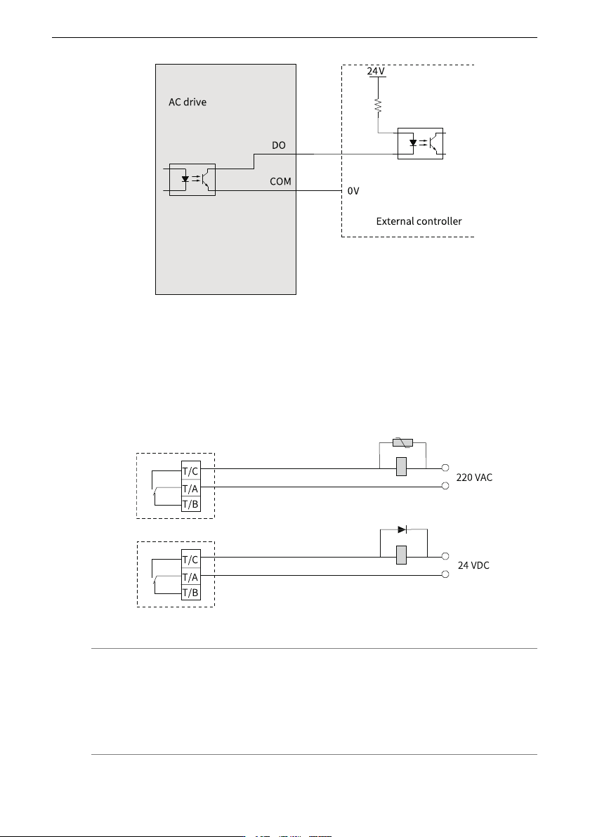
DO: Optocoupler isolation; unipolarity open collector output
Output voltage range: 0 V to 24 V
Output current range: 0 mA to 50 mA
The DO is a single-polarity terminal and can be wired only in the following way.
The DO does not require the internal 24 V power supply.
Wiring
‑77‑
Figure 6‑13 DO connecting to external controller
Wiring of Relay Output Terminals
The inductive load (relay, contactor, and motor) causes voltage peak after the current is
removed. To minimize the interference at cutoff, connect a voltage dependent resistor to
the relay contact and connect absorption circuits, such as voltage dependent resistors,
RC absorption circuits, and diodes, to other inductive loads, as shown in
"Figure 6–14
Anti-interference treatment for relay output terminals
"
on page 77
.
Figure 6‑14 Anti-interference treatment for relay output terminals
Note
● The power supply connected with the control circuit must use class 2 power
supply; otherwise, the operation performance of the AC drive will be degraded.
● For control cable specifications, see "Control Circuit Cable" in MD600 Series
Compact AC Drive User Guide.