MD600 Series Compact AC Drive Hardware Guide-EN-B06.PDF - 第31页
Electrical Design ‑ 30 ‑ Cable list The cable list mainly includes the cable type, name, and appearance, as shown in the following table. Table 4–1 List of Cables Type Cable Illustration Type Cable Illustration Main circ…
Electrical Design
‑29‑
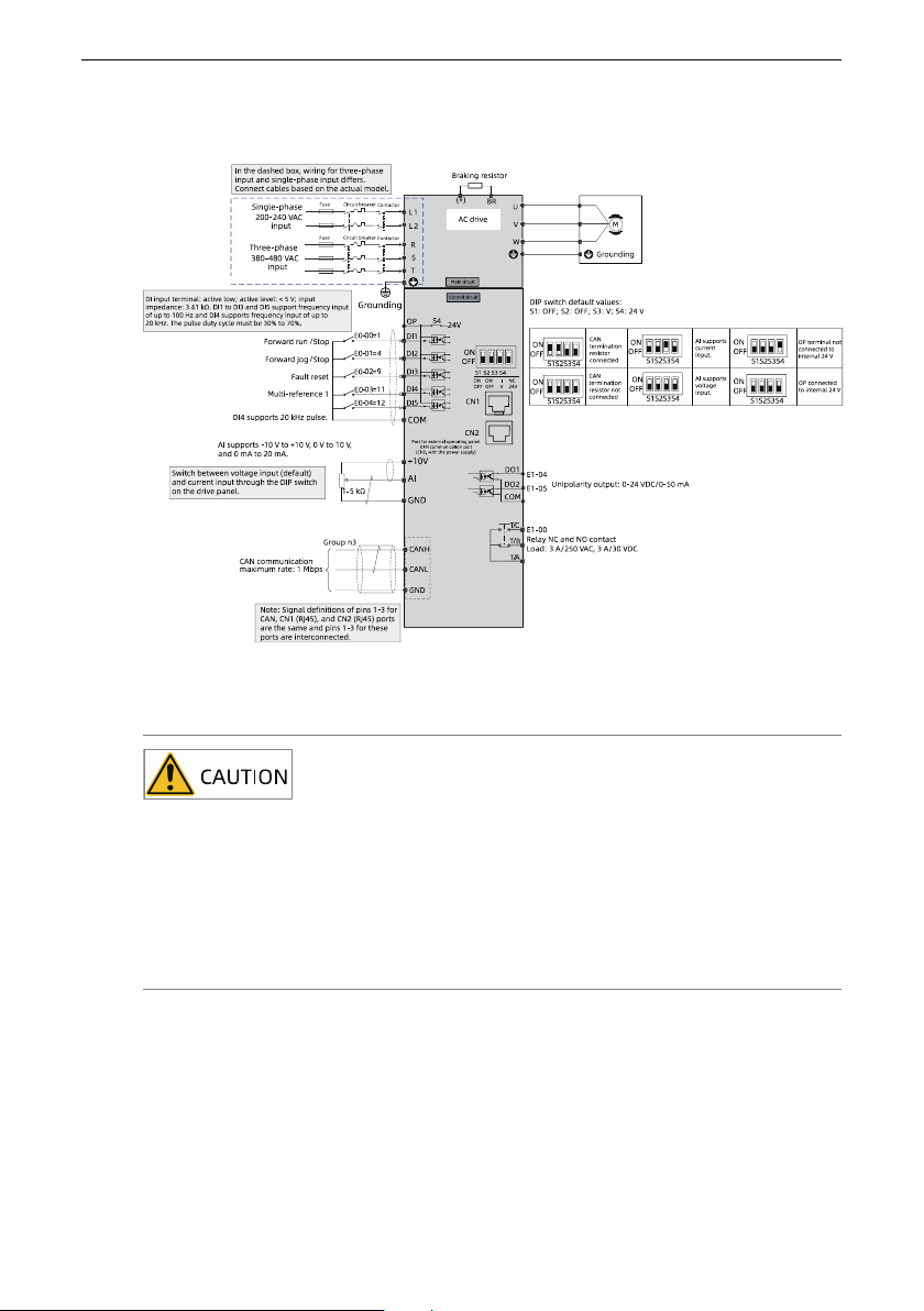
Wiring diagram for the MD600 (CAN model)
Figure 4‑2 Input terminals of three‑phase/single‑phase power supply
● Signal interference may cause malfunctions. Therefore, keep the signal cable at
least 20 cm away from the power cable and separately configure the input and
output sides of the main circuit.
● Do not leave cuttings inside the drive while wiring. Failure to comply may result
in errors, faults, and malfunctions.
● Keep the drive clean. Do not drop cuttings or dust into the drive while drilling
mounting holes on the control cabinet.
4.2 Cable Preparations
During the electrical design phase, you need to prepare cables according to the cable list
and cable preparation.
Electrical Design
‑30‑
Cable list
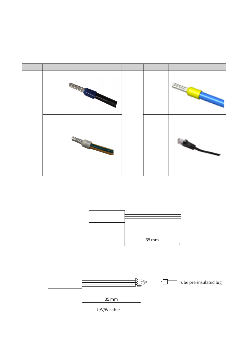
The cable list mainly includes the cable type, name, and appearance, as shown in the
following table.
Table 4–1 List of Cables
Type
Cable Illustration
Type
Cable Illustration
Main
circuit
cable
Power
cable
Control
circuit
cable
Signal cable
Grounding
cable
Network
cable
Cable preparation
To prepare the cable, do as follows:
1. Strip the cable rubber sheath to the length shown in the figure below.
Figure 4‑3 Cable preparation 1
2. Prepare lugs for U/V/W cables and grounding cables according to the following length
requirements.
Figure 4‑4 Cable preparation 2

Electrical Design
‑31‑
4.3 Basic Electrical Safety Precautions
4.3.1 Selecting Power Supply Isolation Devices
Install a manually operated input isolation device between the AC power supply and the
AC drive. Disconnecting the isolation device can cut off the power supply for safety
during installation and maintenance.
EU
To comply with the EU guidelines, the isolation device must be one of the following types
according to electrical safety standards for machinery equipment specified in EN60204-1:
● Isolation switch (EN 60947-3) of AC-23B
● Circuit breaker for isolation which complies with EN 60947-2
Other regions
The isolation device must comply with the applicable safety regulations.
4.3.2 Selecting Main Contactors
If the main contactor is used, the type (number of operation times under load) must be
AC-1 and must be in accordance with IEC 60947-4. Select the contactor based on the
rated voltage and current of the AC drive.
4.3.3 Short-circuit protection
When the AC drive encounters an internal short circuit fault, the fuse used to protect the
AC drive will prevent damage to the AC drive and the adjacent devices.
If the motor cable size is determined according to the rated current of the AC drive, the AC
drive can protect the motor cable and motor in case of short circuit. No other protective
equipment is required.
4.3.4 Selecting Motors
After power-on, the motor generates heat continuously due to thermal effect of the
current. The heat is then dissipated to the surroundings. When the generated heat
exceeds the dissipated heat, the motor temperature rises, which will burn the motor.
The drive provides motor overload protection, but does not provide motor overheat
protection. Therefore, use a motor with the overheat detection function.