MD600 Series Compact AC Drive Hardware Guide-EN-B06.PDF - 第30页
Electrical Design ‑29‑ Wiring diagram for the MD600 (CAN model) Figure 4‑2 Input terminals of three‑phase/single‑phase power supply ● Signal interference may cause malfunctions. Therefore, keep the signal cable at least …
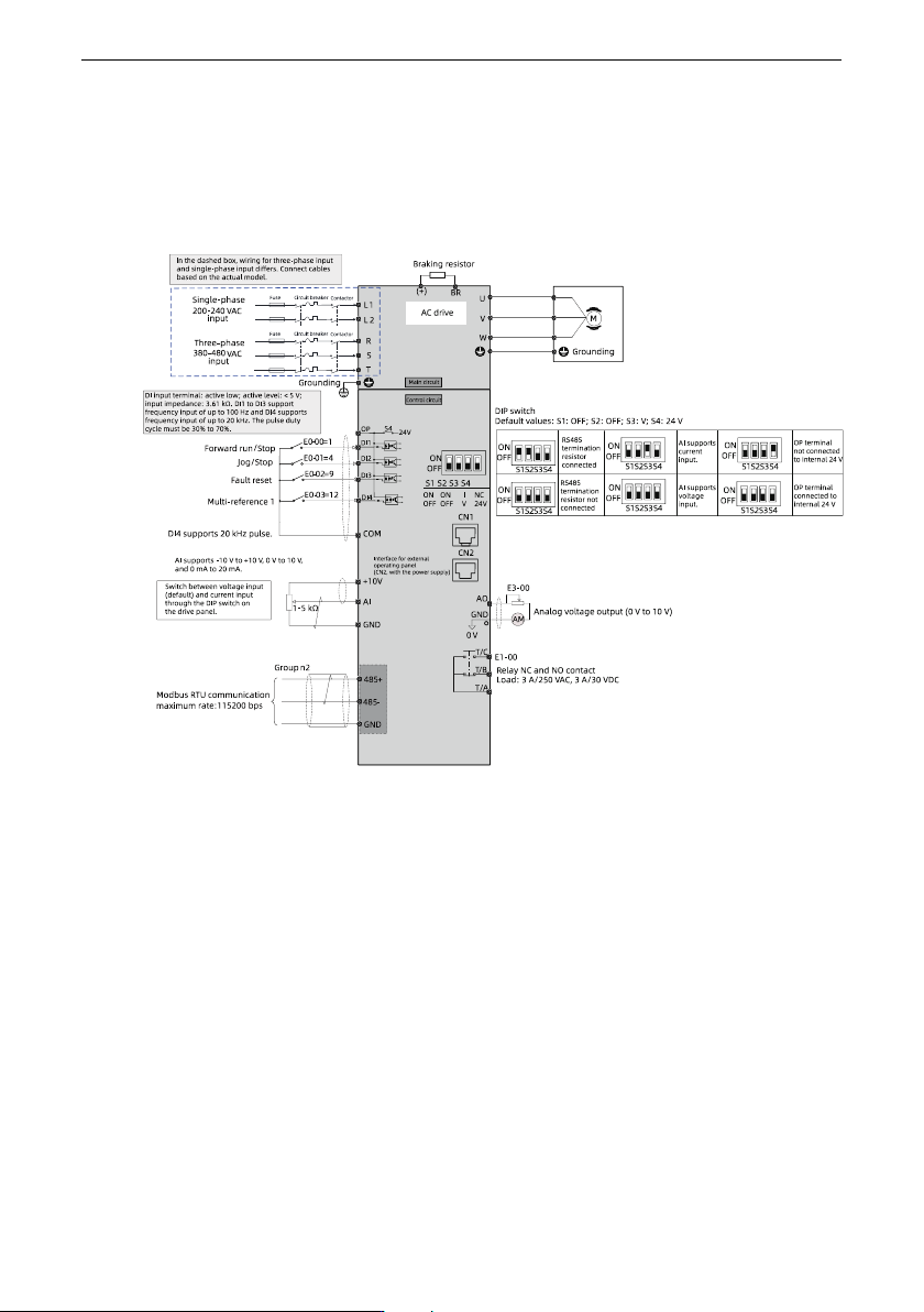
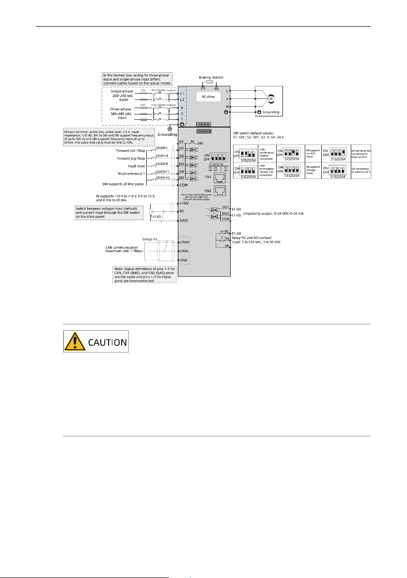
Electrical Design
‑29‑
Wiring diagram for the MD600 (CAN model)
Figure 4‑2 Input terminals of three‑phase/single‑phase power supply
● Signal interference may cause malfunctions. Therefore, keep the signal cable at
least 20 cm away from the power cable and separately configure the input and
output sides of the main circuit.
● Do not leave cuttings inside the drive while wiring. Failure to comply may result
in errors, faults, and malfunctions.
● Keep the drive clean. Do not drop cuttings or dust into the drive while drilling
mounting holes on the control cabinet.
4.2 Cable Preparations
During the electrical design phase, you need to prepare cables according to the cable list
and cable preparation.
Electrical Design
‑30‑
Cable list
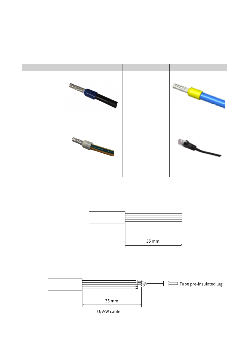
The cable list mainly includes the cable type, name, and appearance, as shown in the
following table.
Table 4–1 List of Cables
Type
Cable Illustration
Type
Cable Illustration
Main
circuit
cable
Power
cable
Control
circuit
cable
Signal cable
Grounding
cable
Network
cable
Cable preparation
To prepare the cable, do as follows:
1. Strip the cable rubber sheath to the length shown in the figure below.
Figure 4‑3 Cable preparation 1
2. Prepare lugs for U/V/W cables and grounding cables according to the following length
requirements.
Figure 4‑4 Cable preparation 2