MD600 Series Compact AC Drive Hardware Guide-EN-B06.PDF - 第108页
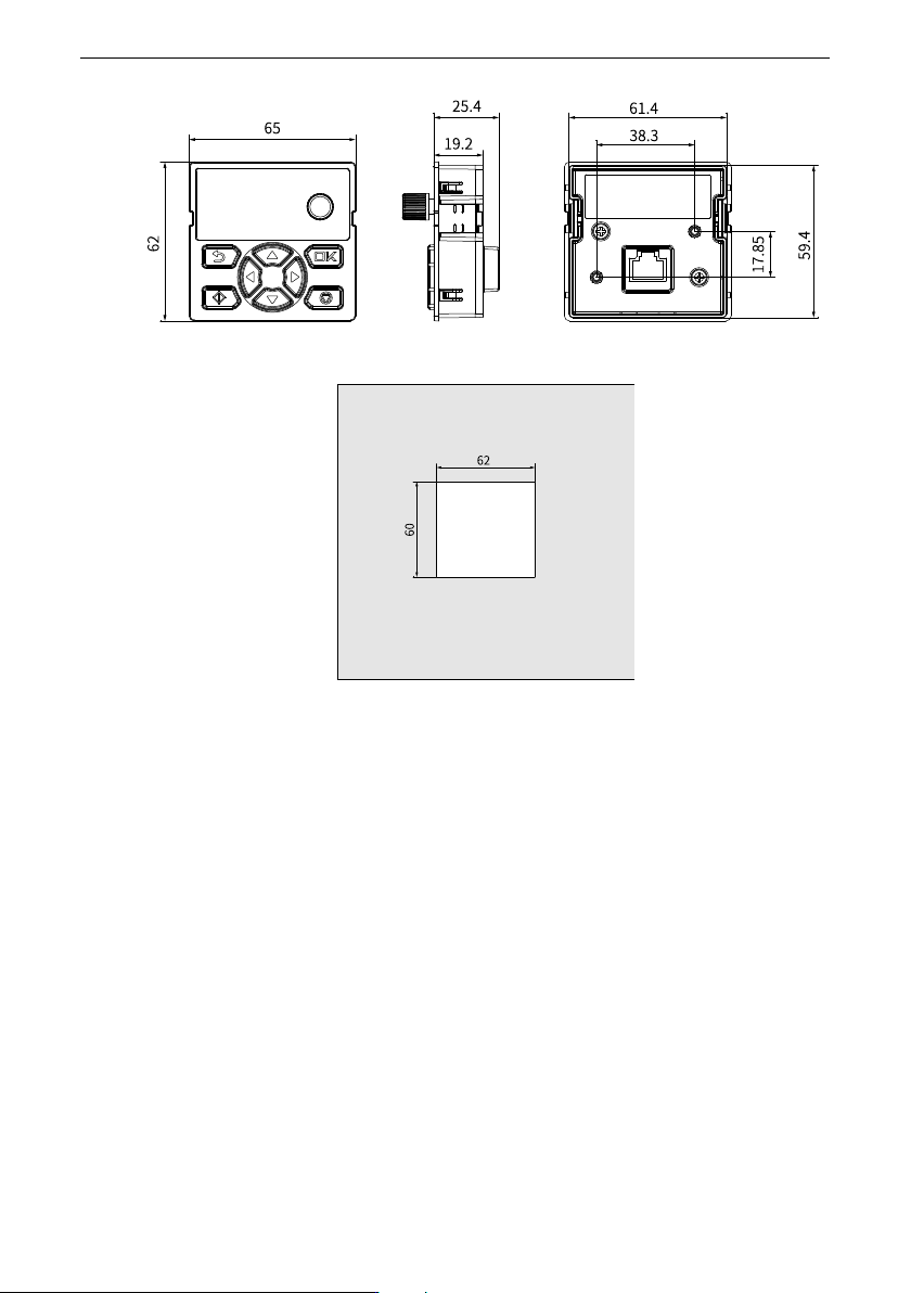
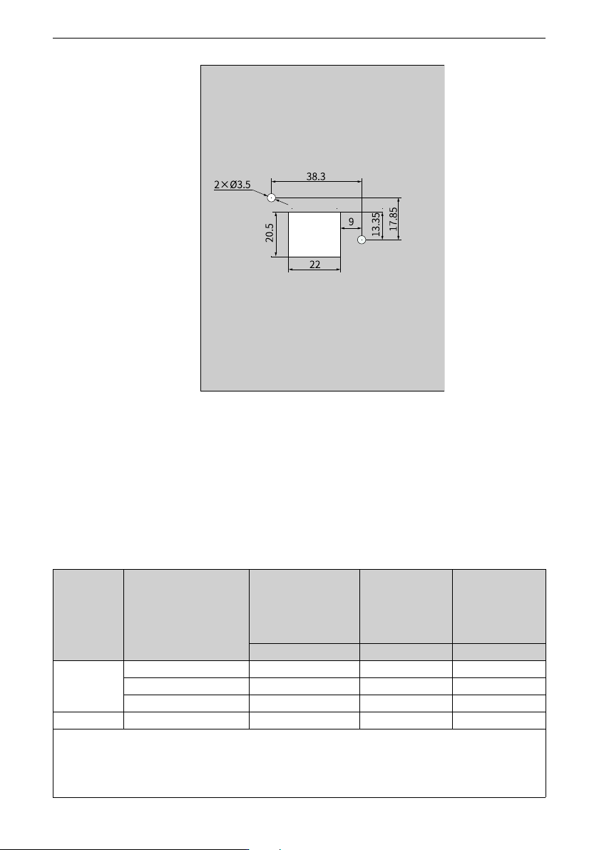
Option ‑107‑ Figure 12‑5 Dimensions (unit: mm) of the cabinet door opening for mounting the MD-BP- M with screws 12.3 Circuit Breaker and Fuse (CE) The following tables list recommended circuit breakers, fuses, and elect…
Option
‑107‑
Figure 12‑5 Dimensions (unit: mm) of the cabinet door opening for mounting the MD-BP-
M with screws
12.3 Circuit Breaker and Fuse (CE)
The following tables list recommended circuit breakers, fuses, and electromagnetic
contactors.
Table 12–2 Circuit breaker, fuse, and electromagnetic contactor (single-phase 200 V to 240 V,
compliance with CE)
Structure Model
Recommended
Semiconductor Fuse
Specification
(Bussmann)
Recommended
Contactor
Specification
(Schneider)
Minimum
Specification of
Recommended D-
Type Circuit Breaker
(Schneider)
Rated current (A) Rated current (A) Rated current (A)
T1
MD600S/A–2S2R8(B)
10 9 10
MD600S/A–2S4R6(B)
15 12 16
MD600S/A–2S7R5(B)
25 18 25
T2
MD600S/A–2S010(B)
35 25 32
The recommended values in the preceding table are based on the following prerequisites:
1. The ambient temperature of the device is 40℃ and there is no forced air cooling method. The altitude is 2000 m. Only
a single drive is installed. The current-carrying density of the conductor is 1.3 A/mm².
2. If the conditions vary, select the model according to actual conditions.
Option
‑108‑
Table 12–3 Circuit breaker, fuse, and electromagnetic contactor (three-phase 380 V to 480 V, com-
pliance with CE)
Structure Model
Recommended
Semiconductor Fuse
Specification (Bussmann)
Recommended
Contactor
Specification
(Schneider)
Minimum
Specification of
Recommended D-
Type Circuit Breaker
(Schneider)
Rated current (A) Rated current (A) Rated current (A)
T1
MD600S/A‑4T1R6(B)
5 9 3
MD600S/A–4T2R3(B)
5 9 4
MD600S/A–4T4R8(B)
10 9 10
MD600S/A–4T5R5(B)
15 9 10
T2
MD600S/A–4T9R5(B)
20 12 16
MD600S/A‑4T013(B)
25 18 25
The recommended values in the preceding table are based on the following prerequisites:
1. The ambient temperature of the device is 40℃ and there is no forced air cooling method. The altitude is 2000 m. Only
a single drive is installed. The current-carrying density of the conductor is 1.3 A/mm².
2. If the conditions vary, select the model according to actual conditions.
12.4 AC input reactor
The AC input reactor is mainly used to reduce harmonics in the input current. As an
option, installing the input reactor on the input side of the AC drive can improve the input
power factor, suppress the high harmonics of the input current of the AC drive, and
reduce external conduction and radiation interference. When the application
environment has high requirements on grid harmonics suppression, you can choose an
optional reactor as required.
Inovance AC output reactor
Recommended AC input reactor manufacturers and models are listed in the following
tables.
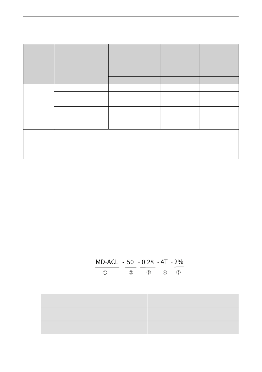
Figure 12‑6 AC input reactor model
①
Internal code
MD-ACL: Inovance AC input reactor
④
Rated voltage
4T: 380V
②
Rated current
50: 50 A
⑤
Voltage drop percentage
2%: 2%
③
Inductance
0.28: 0.28 mH
-