MD600 Series Compact AC Drive Hardware Guide-EN-B06.PDF - 第52页
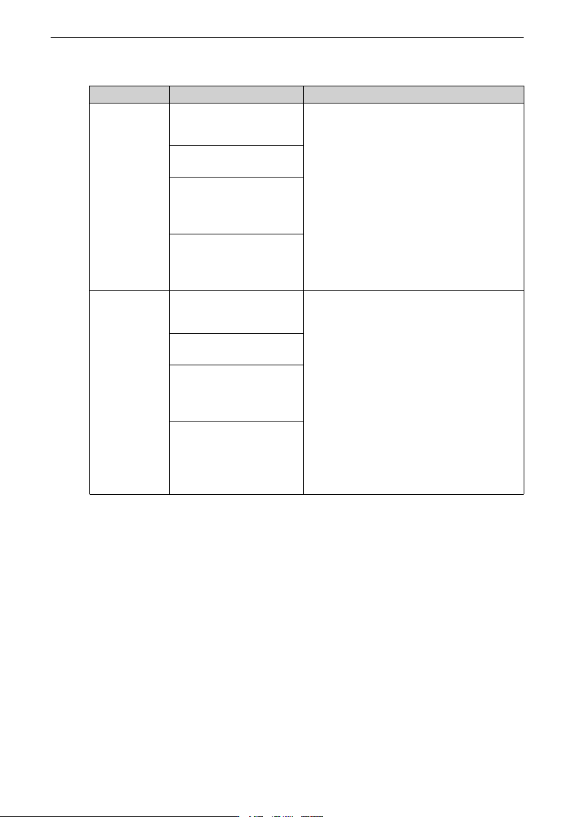
Electrical Design ‑51‑ Table 4–15 Troubleshooting when the ELCB malfunctions Symptom Possible cause Solution The RCD trips at the moment of power-on. The anti-interference performance of the RCD is weak. 1. Use RCDs of r…
Electrical Design
‑50‑
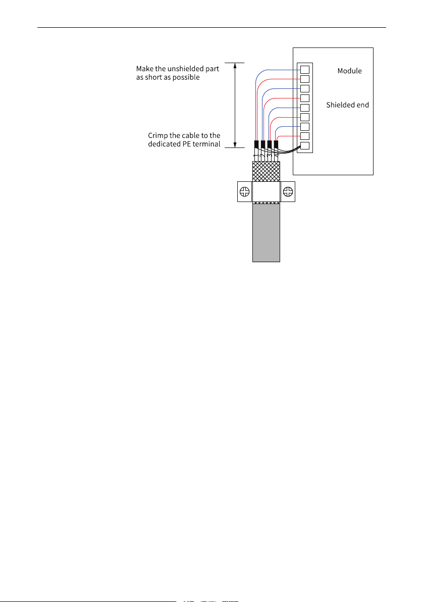
Figure 4‑17 Requirements on shielded cable
4.6 Solutions to Common EMC Issues
4.6.1 Harmonic Suppression Measures
To suppress the high harmonic current of this product and improve the power factor,
install an AC input reactor on the input side of the product. This will enable the product to
meet standard requirements.
4.6.2 Residual Current Device Misoperation
When malfunction occurs on the residual current device (RCD), take the following
measures.
Electrical Design
‑51‑
Table 4–15 Troubleshooting when the ELCB malfunctions
Symptom
Possible cause Solution
The RCD trips
at the moment
of power-on.
The anti-interference
performance of the RCD is
weak.
1. Use RCDs of recommended brands.
2. Use an RCD with a higher tripping
current.
3. Move the unbalanced load to the
upstream side of the residual current
device.
The tripping current of the
RCD is excessively low.
An unbalanced load is
connected to the
downstream side of the
RCD.
An excessive ground
capacitance exists in the
upstream side of the
drive.
The RCD trips
during
operation.
The anti-interference
performance of the RCD is
weak.
1. Use RCDs of recommended brands.
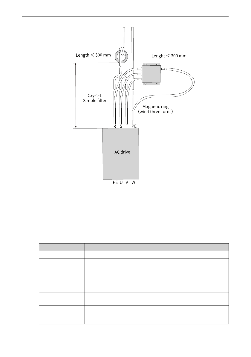
2. Install a simple filter on the input side of
the drive and wind the LN and RST
cables through the ferrite ring near the
RCD, as shown in
"Figure 4–18 Installing
simple filter and ferrite ring on the input
side
"
on page 52
.
3. Use an RCD with a higher rated tripping
current.
4. Reduce the carrier frequency without
compromising the performance.
5. Use shorter motor cables.
The tripping current of the
RCD is excessively low.
An unbalanced load is
connected to the
downstream side of the
RCD.
The distributed
capacitance to ground of
the motor cable and
motor is excessively high.
Electrical Design
‑52‑
Figure 4‑18 Installing simple filter and ferrite ring on the input side
4.6.3 I/O Signal Interference
4.6.3.1 High-speed Pulse Interference
Take the measures listed in the following table.
No. Step
1
Use shielded twisted pair cables and ground both ends.
2
Connect the motor housing to the PE of the AC drive.
3
Connect the PE of the AC drive to the PE of the mains power
supply.
4
Add an equipotential bonding grounding cable between the host
controller and the drive.
5
Separate signal cables from power cables with a distance of at
least 20 cm.
6
Add a ferrite clamp to the signal cable, or add a magnetic ring
and wind the signal cable through the magnetic ring for one to
two turns.