MD600 Series Compact AC Drive Hardware Guide-EN-B06.PDF - 第47页
Electrical Design ‑ 46 ‑ Figure 4‑10 Cabling diagram ● Requirements on cabling I/O signal cables I/O signals include analog input (AI), analog output (AO), digital input (DI), digital output (DO) and relay output signals…
Electrical Design
‑45‑
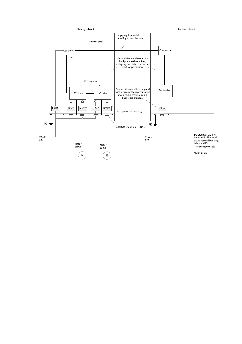
Figure 4‑9 Recommended wiring of the cabinet system
Routing Precautions
● Main circuit cabling requirements
The power supply input cable of the AC drive and motor cable can generate strong
electromagnetic interference. To avoid electromagnetic interference caused by long-
distance parallel coupling between the strong disturbing cable and control circuit,
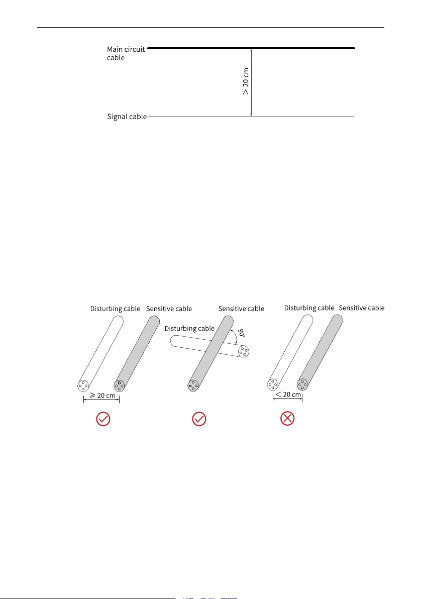
ensure a distance longer than 20 cm between main circuit cables and signal cables
when cabling. Main circuit cables include the input R/S/T cable, output U/V/W cable,
DC bus, and braking cable. Signal cables include the I/O signal cable and
communication cable.
Cable ducts must be in good connection and well grounded. Aluminum cable ducts
can be used to ensure equipotentiality of the device. Connect the AC drive and motor
to the system (machines or devices) properly. Protect all connections with spray
coating and ensure good contact of conductive metal.
Electrical Design
‑46‑
Figure 4‑10 Cabling diagram
● Requirements on cabling I/O signal cables
I/O signals include analog input (AI), analog output (AO), digital input (DI), digital
output (DO) and relay output signals. To avoid interference to the I/O signals,
separate the I/O signal cables at least 20 cm from the main circuit cables (R/S/T
cables and U/V/W cables) and other power cables or power supply cables.
Routing recommendations
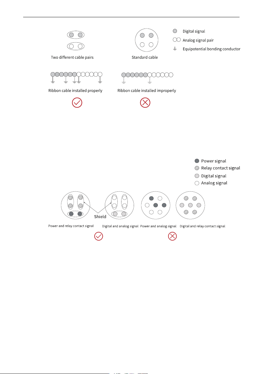
● Routing of disturbing cables and sensitive cables
During routing, route cables that transmit different types of signals through different
routes. Separate the disturbing cables from sensitive cables by a distance of 20 cm
wherever possible. When two types of cables must be intersected, the intersection
angle must be 90 degrees to avoid interference, as shown in the following figure.
Figure 4‑11 Routing of disturbing cables and sensitive cables
● Routing of cables transmitting different types of signals
Route cables that transmit different types of signals through different routes and
separate them with equipotential signal cables. When routing cables that transmit the
same type of signals, the equipotential signal cable stays in the outer layer and
equipotential signals should stay in the middle if possible, as shown in the following
figure.
Electrical Design
‑47‑
Figure 4‑12 Routing different types of signal cables
● Routing of multi-conductor cables
Use one multi-conductor cable to transmit one type of signals. If you need to use one
multi-conductor cable to transmit different types of signals, isolate the conductors
that transmit one type of signals, as shown in the following figure.
Figure 4‑13 Routing of multi-conductor cables
If certain conductors in a multi-conductor cable are reserved or unused, connect these
conductors to the equipotential bonding point, as shown below.