MD600 Series Compact AC Drive Hardware Guide-EN-B06.PDF - 第128页
Option ‑127‑ Table 12–21 Cable selection (three-phase 380 V to 480 V, compliant with CE certification) Three-phase 380 V to 480 V AC drive model Power (kW) Rated input cur rent (A) Rated out put cur rent Braking current …
Option
‑126‑
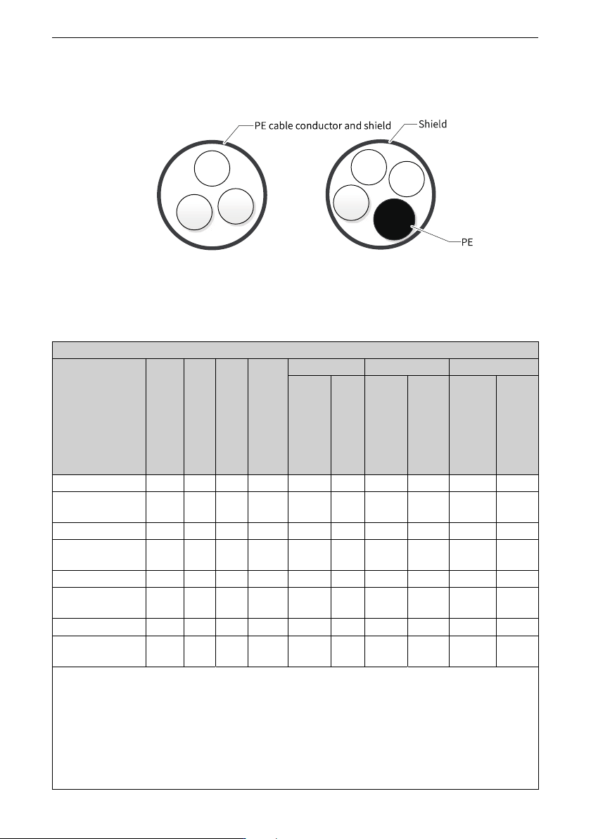
containing a PE conductor. The shield of the shielded cable consists of coaxial cooper
braids to suppress radio frequency interference. The braided density of the cooper braid
should be greater than 90% to enhance the shielding efficiency and conductivity.
Figure 12‑16 Recommended power cable types
Recommended cable
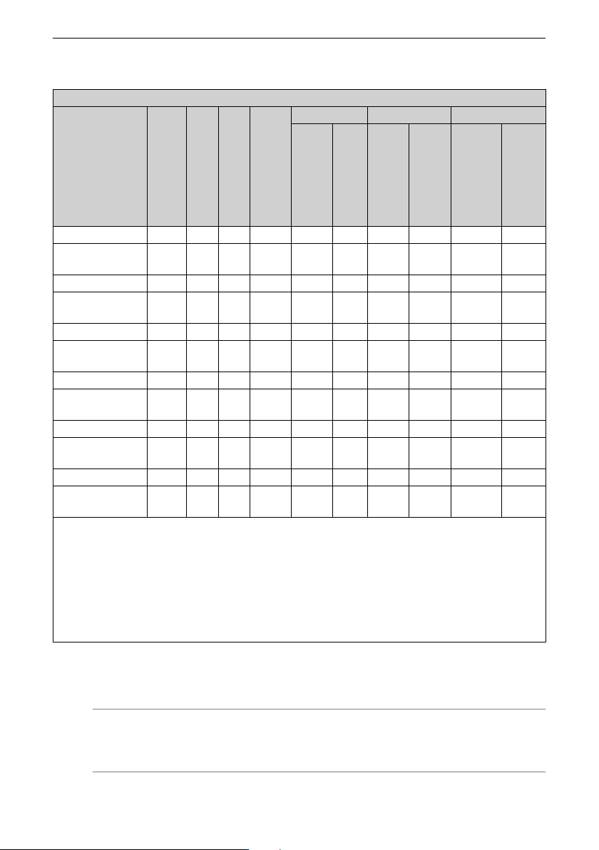
Table 12–20 Cable selection (single-phase 200 V to 240 V, compliant with CE certification)
Single-phase 200 V to 240 V
AC drive model Power
(kW)
Rated
input
cur
rent
(A)
Rated
out
put
cur
rent
Braking
current
(A)
RST/UVW Grounding cable Braking terminal
Recom
mended
cable
type
(mm
2
)
[1]
Rec
om
mend
ed
termi
nal
model
Recom
mended
cable
type
(mm
2
)
[1]
Recom
mended
termi
nal
model
Recom
mended
cable
type
(mm
2
)
[1]
Recom
mended
terminal
model
MD600S/A-2S2R8(B) 0.37 6.2 2.8 0.71 3x0.75 E7510 0.75 E7510 0.75 E7510
MD600S/A-2S2R8 0.37 6.2 2.8 No
braking
3x0.75 E7510 0.75 E7510 / /
MD600S/A-2S4R6(B) 0.75 10.2 4.6 1.43 3x1 E1010 1 E1010 0.75 E7510
MD600S/A-2S4R6 0.75 10.2 4.6 No
braking
3x1 E1010 1 E1010 / /
MD600S/A-2S7R5(B) 1.5 16.6 7.5 2.87 3x2.5 E2510 2.5 E2510 0.75 E7510
MD600S/A-2S7R5 1.5 16.6 7.5 No
braking
3x2.5 E2510 2.5 E2510 / /
MD600S/A-2S010(B) 2.2 22.2 10 4.2 3x4 E4012 4 E4012 0.75 E7510
MD600S/A-2S010 2.2 22.2 10 No
braking
3x4 E4012 4 E4012 / /
Notes:
[1]: Chinese standards applicable; 3 x 4: one three-conductor cable with a cross sectional area of 4 mm
2
. It is
recommended to use the tube pre-insulated lugs (TG-JT type) produced by Zhejiang KISE Terminal Co., Ltd.
1. Observe the local regulations during selection. The cables recommended in the preceding table meet the following
conditions:PVC insulation and copper conductor. Heat resistance: maximum cable surface temperature not
exceeding 70°C at an ambient temperature of 40°C (Remark: When the ambient temperature exceeds 40°C, contact
Inovance.) Cable layout type E is adopted (see IEC 60204-1).
2. If the conditions vary, select the model according to actual conditions.
Option
‑127‑
Table 12–21 Cable selection (three-phase 380 V to 480 V, compliant with CE certification)
Three-phase 380 V to 480 V
AC drive model Power
(kW)
Rated
input
cur
rent
(A)
Rated
out
put
cur
rent
Braking
current
(A)
RST/UVW Grounding cable Braking terminal
Recom
mend
ed
cable
type
(m
m
2
)
[1]
Rec
om
mend
ed
termi
nal
model
Recom
mend
ed
cable
type
(m
m
2
)
[1]
Recom
mended
terminal
model
Recom
mended
cable type
(mm
2
)
[1]
Recom
mended
terminal
model
MD600S/A-4T1R6(B) 0.37 1.9 1.6 0.34 3x0.75 E7510 0.75 E7510 0.75 E7510
MD600S/A-4T1R6 0.37 1.9 1.6 No
braking
3x0.75 E7510 0.75 E7510 / /
MD600S/A-4T2R3(B) 0.75 2.8 2.3 0.7 3x0.75 E7510 0.75 E7510 0.75 E7510
MD600S/A-4T2R3 0.75 2.8 2.3 No
braking
3x0.75 E7510 0.75 E7510 / /
MD600S/A-4T4R8(B) 1.5 5.9 4.8 1.4 3x0.75 E7510 0.75 E7510 0.75 E7510
MD600S/A-4T4R8 1.5 5.9 4.8 No
braking
3x0.75 E7510 0.75 E7510 / /
MD600S/A-4T5R5(B) 2.2 6.7 5.5 2.05 3x0.75 E7510 0.75 E7510 0.75 E7510
MD600S/A-4T5R5 2.2 6.7 5.5 No
braking
3x0.75 E7510 0.75 E7510 / /
MD600S/A-4T9R5(B) 4 11.6 9.5 3.72 3x1.5 E1512 1.5 E1512 0.75 E7510
MD600S/A-4T9R5 4 11.6 9.5 No
braking
3x1.5 E1512 1.5 E1512 / /
MD600S/A-4T013(B) 5.5 15.8 13 5.12 3x2.5 E2512 2.5 E2512 0.75 E7510
MD600S/A-4T013 5.5 15.8 13 No
braking
3x2.5 E2512 2.5 E2512 / /
Notes:
[1]: Chinese standards applicable; 3 x 4: one three-conductor cable with a cross sectional area of 4 mm2. It is
recommended to use the tube pre-insulated lugs (TG-JT type) produced by Zhejiang KISE Terminal Co., Ltd.
1. Observe the local regulations during selection. The cables recommended in the preceding table meet the following
conditions:PVC insulation and copper conductor. Heat resistance: maximum cable surface temperature not
exceeding 70°C at an ambient temperature of 40°C (Remark: When the ambient temperature exceeds 40°C, contact
Inovance.) Cable layout type E is adopted (see IEC 60204-1).
2. If the conditions vary, select the model according to actual conditions.
12.9.2Control Circuit Cables
Note
Wire the control circuit cable according to EN 60204-1.
Option
‑128‑
To ensure that I/O signal cables are not affected by peripheral interference and noise,
use shielded cables as signal cables. Install the signal shield bracket at each end of the
shield to bond the shield to the drive 360 degrees. Use separate shielded cables for
different analog signals. It is recommended to use shielded twisted pair (STP) cables for
digital signals.
Figure 12‑17 Shielded twisted pair cables
Table 12–22 Specifications of the control circuit cable
Structure Type
Recommended IEC
Cable Specification
(mm
2
)
Recommended cable lug
specifications
T1
Control signal terminal
0.5–1.0 IEC:
● 0.5 mm
2
(E0510)
● 0.75 mm
2
(E7510)
● 1 mm
2
(E1010)
Relay terminal
0.5–1.0
T2
Control signal terminal
0.5–1.0
Relay terminal
0.5–1.0
12.9.3Terminal
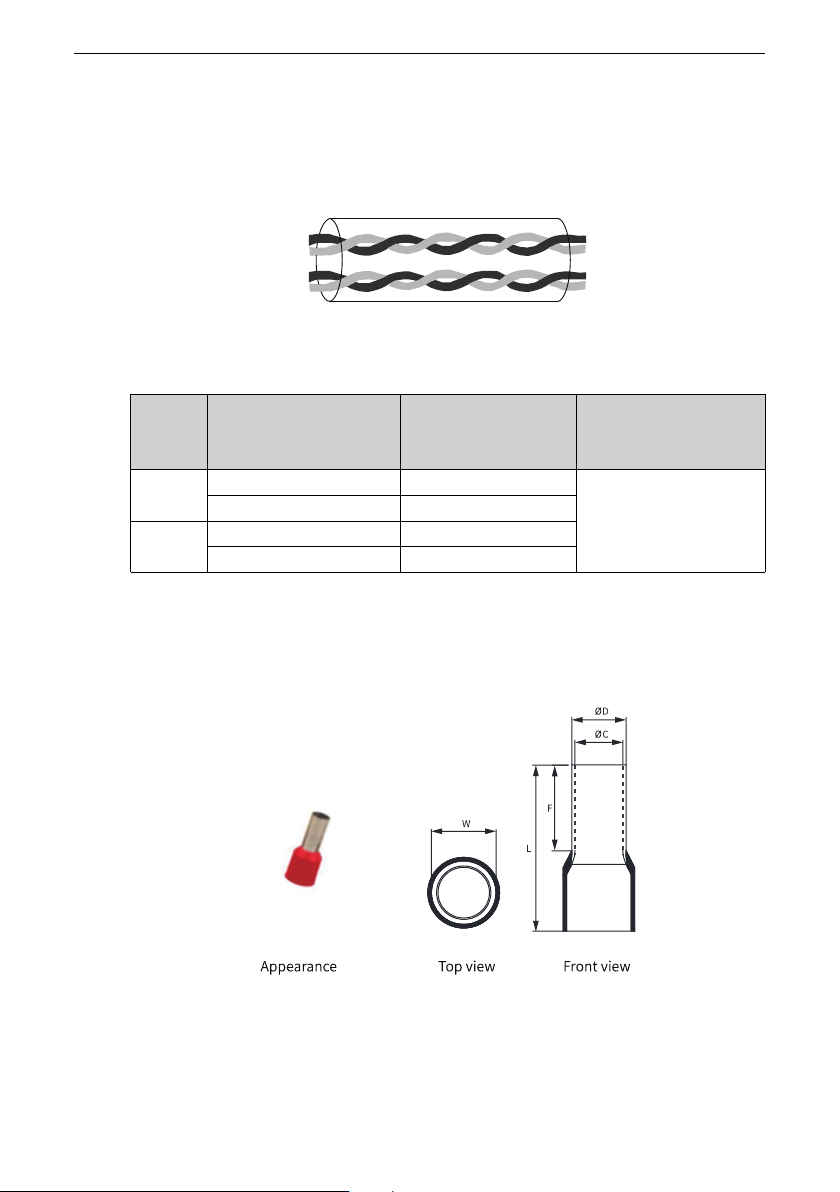
It is recommended to use the terminals produced by Zhejiang KISE Terminal Co., Ltd., that
is, the tube pre-insulated terminal (TG-JT type).
Figure 12‑18 Appearance and dimensions of the tube-type pre-insulated terminal (TG-JT)