MD600 Series Compact AC Drive Hardware Guide-EN-B06.PDF - 第34页
Electrical Design ‑33‑ 4.4 Electromagnetic Compatibility Overview Electromagnetic compatibility (EMC) means that a device or system can work normally in its electromagnetic environment and the device or system does not e…

Electrical Design
‑32‑
Use the dedicated motor for the AC drive. Failure to comply will result in short circuit due
to insulation.
4.3.5 Checking the Compatibility of the Motor and Drive
The AC drive can be used to drive one or multiple AC asynchronous induction motors
simultaneously. According to AC voltage and motor load, select the motor capacity and
drive model according to
"11.3 Electrical Specifications
"
on page 94
.
4.3.6 Selecting SPD Surge Protection Devices
The surge protection device (SPD) is installed on the input side of the AC drive to ensure
that electrical systems and important electrical and electronic equipment are protected
from damage caused by lightning overvoltage. The SPD is mainly used to limit transient
overvoltage and operating overvoltage caused by lightning in power supply and signal
systems. Lightning surges can be transmitted to the AC drive through the power supply or
signal cable. When a lightning stroke occurs, the ground potential increases, which may
damage the drive. The induced voltage can be produced in the cable and loop when a
pulse electromagnetic field is generated by a lightning strike on the building (or in the
vicinity). Therefore, in addition to the external lightning protection measures such as the
installation of lightning rods, down conductors, and grounding devices, you need to
install an SPD. This is because the lightning rod, down conductor, and grounding device
cannot prevent conduction of lightning induction surge along the cable and secondary
lightning strike.
4.3.7 Requirements on Power Grid System Compatibility
When the power supply distribution system of the AC drive is an asymmetric grounding
system or a floating ground system (IT system), remove the ground safety capacitor for
grounding applications. Any voltage to ground of the asymmetric grounding system or
floating ground system (IT system) may exceed the voltage of the built-in filter and safety
capacitor. Therefore, connecting to ground in this system will damage the AC drive.
To avoid risks or accidents, it is not recommended to use the AC drive in an asymmetric
grounding system or in a floating ground system (IT system).
The AC drive supports only TN and TT star-type power grids under normal conditions.
Other power grids are not supported. Contact Inovance technical service personnel if
necessary.

Electrical Design
‑33‑
4.4 Electromagnetic Compatibility
Overview
Electromagnetic compatibility (EMC) means that a device or system can work normally in
its electromagnetic environment and the device or system does not emit electromagnetic
interference (EMI) that causes abnormal operation of other devices or systems in the
environment.
Category
Electromagnetic compatibility performance of the drive includes two aspects:
electromagnetic emission (EMI) and electromagnetic sensitivity (EMS). EMI includes
radiated emission (RE) and conducted emission (CE).
● Radiated emission (RE): interference signal radiated by the product through the port
on its housing.
● Conducted emission (CE): interference signal conducted from the product through its
cable port.
Interference and Anti-interference
Electromagnetic compatibility is a system-level concept, which indicates that the product
has certain anti-interference capabilities and does not seriously interfere with other
devices.
4.5 Cabinet Design
4.5.1 Recommended Cabinet Layout
Reserve sufficient clearance according to the power rating of the drive. The
recommended installation methods of the MD600 include single-layer installation
and multi-layer installation.
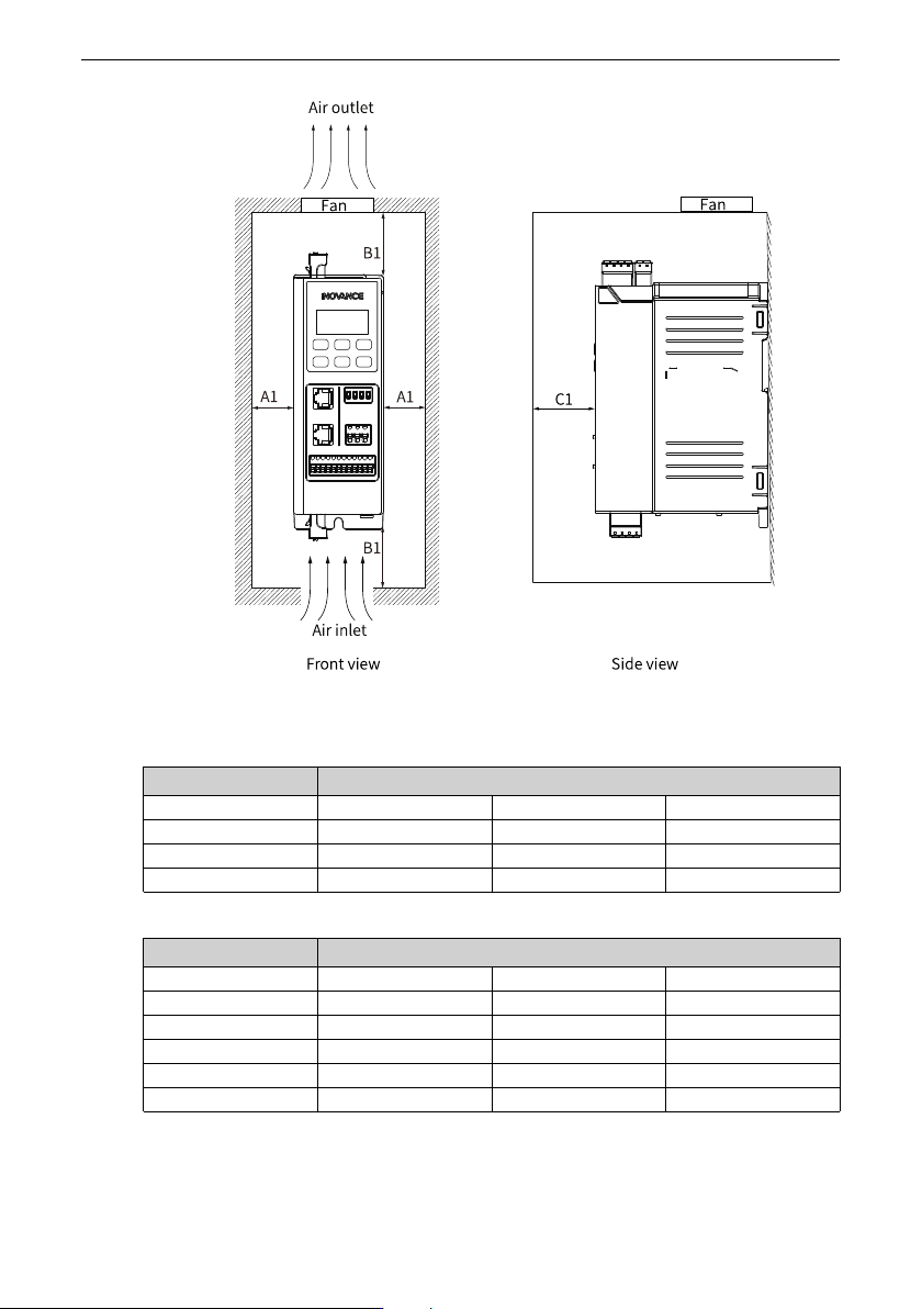
● When only a single device is installed, reserve sufficient clearance around the device,
as shown in the following figure.
Electrical Design
‑34‑
Figure 4‑5 Clearance for installation of a single device
Table 4–2 Clearance for installation of a single device (single-phase 200 V to 240 V)
Power Rating (kW) Clearance (mm)
0.37 A1 ≥ 20 B1 ≥ 100 C1 ≥ 80
0.75 A1 ≥ 20 B1 ≥ 100 C1 ≥ 80
1.5 A1 ≥ 20 B1 ≥ 100 C1 ≥ 80
2.2 A1 ≥ 20 B1 ≥ 120 C1 ≥ 80
Table 4–3 Clearance for installation of a single device (three-phase 380 V to 480 V)
Power Rating (kW) Clearance (mm)
0.37 A1 ≥ 20 B1 ≥ 100 C1 ≥ 80
0.75 A1 ≥ 20 B1 ≥ 100 C1 ≥ 80
1.5 A1 ≥ 20 B1 ≥ 100 C1 ≥ 80
2.2 A1 ≥ 20 B1 ≥ 100 C1 ≥ 80
4 A1 ≥ 20 B1 ≥ 120 C1 ≥ 80
5.5 A1 ≥ 20 B1 ≥ 120 C1 ≥ 80
● When multiple devices are installed side by side, the minimum distance between two
devices is shown below.