MD600 Series Compact AC Drive Hardware Guide-EN-B06.PDF - 第72页
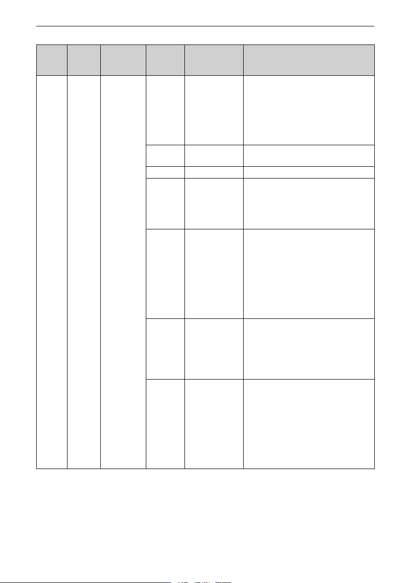
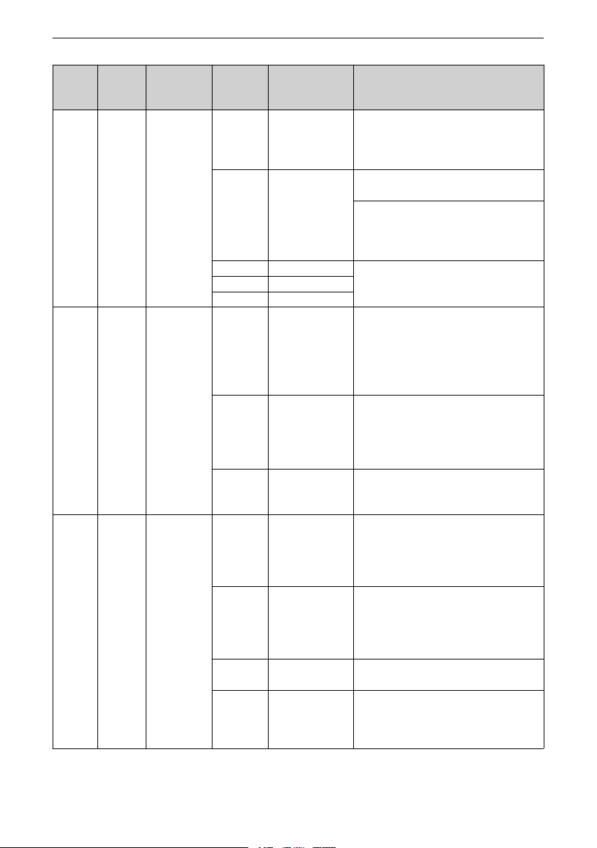
Wiring ‑71‑ External terminal Terminal type Transmission information type Terminal mark Terminal name Function CN4 12-pin terminal block DI/DO/AI/AO/ RS485 485- RS485 communication signal - (RS485 model) Negative RS485 c…
Wiring
‑70‑
External
terminal
Terminal
type
Transmission
information
type
Terminal
mark
Terminal name Function
CN4 12-pin
terminal
block
DI/DO/AI/AO/
RS485
AI1 Analog input
terminal 1
Voltage input of -10 V to +10 V or current
input of 0 mA to 20 mA; 12-bit resolution;
accuracy after correction: 0.3%; response
time: < 2 ms
Input impedance in the voltage input mode:
22 kΩ; input impedance in the current mode:
500 Ω
10V 10 V analog
voltage output
Output voltage range: 10 V ± 5%
Maximum output current: 10 mA
GND Analog ground Internally isolated from COM
AO1 Analog output
terminal 1
(RS485 model)
Voltage output of 0 V to 10 V; 12-bit
resolution; correction accuracy: 0.5%;
maximum load output current in the voltage
output mode: 2 mA; load impedance in the
voltage output mode: 5 kΩ
DO1 Digital output
terminal 1
(CAN model)
Photocoupler isolation; unipolar open
collector output; maximum output
frequency: 100 Hz
It cannot be connected directly to the power
supply. The pull-up resistor with the
resistance set according to the load must be
added.
Output voltage range: 0 V to 24 V
Output current range: 0 mA to 50 mA
485+ RS485
communication
signal +
(RS485 model)
Positive RS485 communication signal;
maximum speed supported by hardware:
115.2 kbps;
Transmission distance: The maximum
transmission distance corresponding to the
baud rate of 9.6 kbps is 1 km.
DO2 DO2
(CAN model)
Photocoupler isolation; unipolar open
collector output; maximum output
frequency: 100 Hz
It cannot be connected directly to the power
supply. The pull-up resistor with the
resistance set according to the load must be
added.
Output voltage range: 0 V to 24 V
Output current range: 0 mA to 50 mA
Wiring
‑71‑
External
terminal
Terminal
type
Transmission
information
type
Terminal
mark
Terminal name Function
CN4 12-pin
terminal
block
DI/DO/AI/AO/
RS485
485- RS485
communication
signal -
(RS485 model)
Negative RS485 communication signal
DI5 DI5
(CAN model)
Isolated sink/source programmable DI; input
frequency: < 100 Hz
The operating voltage ranges from 15 V to 30
V. The voltage lower than 5 V is invalid and
the voltage higher than 15 V is valid. The
input impedance is 3.61 kΩ.
DI1 DI1 See DI5 above.
DI2 DI2
DI3 DI3
CN4 12-pin
terminal
block
DI/DO/AI/AO/
RS485
DI4 DI4 High-speed pulse input terminal (HDI);
maximum input frequency: 20 kHz
The working voltage ranges from 15 V to 30
V. The voltage lower than 5 V is invalid and
the voltage higher than 15 V is valid.
Input impedance: 3.61 kΩ
OP Digital input
power supply
common terminal
It is connected to 24V by default. When DI1 to
DI5 are driven by external signals, connect
OP to COM or the external 24 V power supply,
and disconnect OP from the internal 24V
terminal by setting the S4 DIP switch to ON.
COM Reference ground
of 24 V power
supply
Internally isolated from GND
S - - S1 DIP switch for
termination
resistor for 485+/
CANH
communication
The DIP switch is disconnected by default.
For details, see "
Table 6–4
"
on page 72
S2 DIP switch for
termination
resistor for 485-/
CANL
communication
The DIP switch is disconnected by default.
For details, see "
Table 6–4
"
on page 72
S3 Voltage/current
mode switch for AI
The voltage mode is used by default. For
details, see "
Table 6–4
"
on page 72
S4 24 V power
supply/external
power supply
switch
The 24 V power supply is connected to OP by
default. For details, see "
Table 6–4
"
on page
72
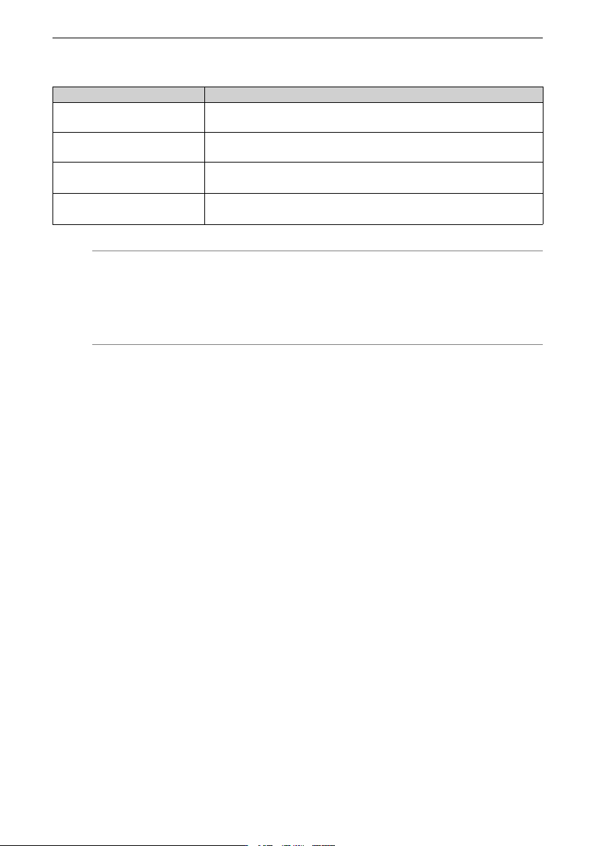
The following table describes DIP switches.
Wiring
‑72‑
Table 6–4 DIP switch definitions
Name Function
S1 ON: Termination resistor connected for RS485/CAN communication
OFF: Termination resistor disconnected for RS485/CAN communication
S2 ON: Termination resistor connected for RS485/CAN communication
OFF: Termination resistor disconnected for RS485/CAN communication
S3 ON: AI1 supports the current input mode (impedance: 500 Ω).
OFF: AI1 supports the voltage input mode.
S4 NC: OP unconnected
24: OP is connected to the internal 24 V power supply.
Note
● By default, the DIP switch is in the OFF position.
● To connect the termination resistor, S1 and S2 must be set to ON at the same
time.
6.3.2 Wiring Descriptions of Control Circuit Terminals
Precautions
I/O signals include analog input (AI), analog output (AO), digital input (DI), digital output
(DO) and relay output signals. To avoid interference to the I/O signals, separate the I/O
signal cables at least 20 cm away from the main circuit cables (R/S/T cables and U/V/W
cables) and other power cables or power supply cables.
Wiring AI1
Weak analog signals are easy to suffer external interference. Therefore, route the analog
cable away from the interference source and keep the cable length as short as possible
(no longer than 20 m). In applications where the analog signal suffers severe
interference, install a filter capacitor or ferrite core at the analog signal source, as shown
in
"Figure 6–7 Wiring of AI terminals
"
on page 73
.